Cirkit Designer
Your all-in-one circuit design IDE
Home /
Project Documentation
Arduino-Controlled Automated Plant Watering System with Soil Moisture Sensing and Daylight-Activated Stepper Motor
Circuit Documentation
Summary
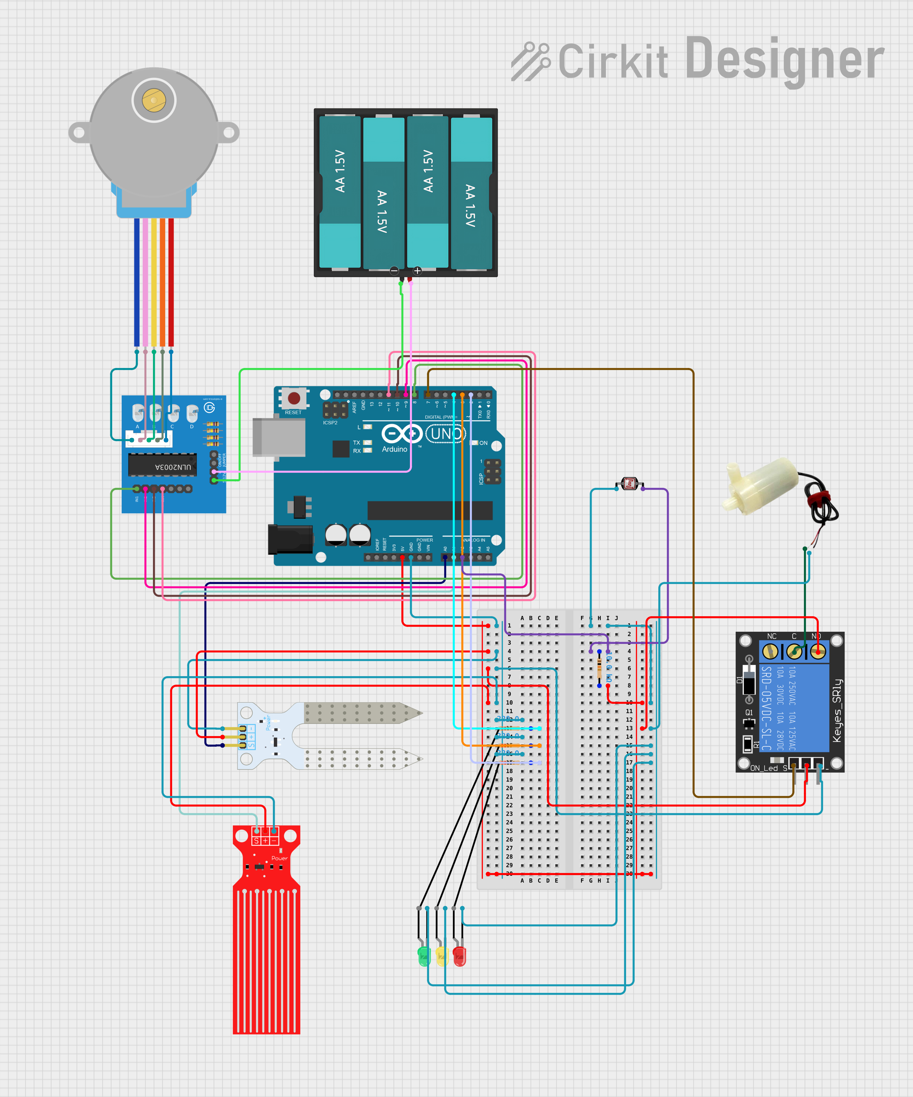
The circuit is designed to monitor and control a plant watering system. It includes sensors for soil moisture and water level, a light-dependent resistor (LDR) for detecting daylight, a relay-controlled water pump, a stepper motor for mechanical movement, and LEDs to indicate water levels. An Arduino UNO microcontroller serves as the central processing unit, interfacing with the sensors, controlling the water pump via a relay, driving the stepper motor through a ULN2003A breakout board, and lighting up LEDs based on water level status.
Component List
Soil Moisture Sensor
- Pins: VCC, GND, SIG
- Description: Measures the moisture level in the soil.
Arduino UNO
- Pins: UNUSED, IOREF, Reset, 3.3V, 5V, GND, Vin, A0-A5, SCL, SDA, AREF, D0-D13
- Description: Microcontroller board used for controlling the various components of the circuit.
1-Channel Relay (5V 10A)
- Pins: NC, signal, C, power, NO, ground
- Description: Acts as an electrically operated switch to control the water pump.
5V Mini Water Pump
- Pins: Positive pin, Negative pin
- Description: Pumps water when activated by the relay.
Water Level Sensor
- Pins: SIG, VCC, GND
- Description: Detects the water level in the reservoir.
28BYJ-48 Stepper Motor
- Pins: BLUE, PINK, YELLOW, ORANGE, RED
- Description: Provides mechanical movement for the system.
ULN2003A Breakout Board
- Pins: In 1-4, 0V, +5V, ON/OFF jumper switch, BLUE wire, PINK wire, YELLOW wire, ORANGE wire, RED wire
- Description: Drives the stepper motor.
Resistor (220 Ohms)
- Pins: Pin1, Pin2
- Description: Limits current to protect LEDs and other components.
LED: Two Pin (Green, Yellow, Red)
- Pins: Cathode, Anode
- Description: Indicates the water level status.
Photocell (LDR)
- Pins: Pin 0, Pin 1
- Description: Senses the ambient light level.
Battery AAx4 6V
- Pins: VCC, GND
- Description: Provides power to the stepper motor and its driver board.
Wiring Details
Soil Moisture Sensor
- VCC: Connected to Arduino 5V
- GND: Connected to Arduino GND
- SIG: Connected to Arduino A0
Arduino UNO
- 5V: Powers the Soil Moisture Sensor, Relay, and Water Level Sensor
- GND: Common ground for various components
- A0: Receives signal from Soil Moisture Sensor
- A1: Receives signal from Water Level Sensor
- A2: Receives signal from LDR
- D2-D4: Connected to LEDs through 220 Ohm resistors
- D7: Controls the Relay signal
- D8-D11: Controls the ULN2003A for stepper motor
1-Channel Relay (5V 10A)
- Power: Connected to Arduino 5V
- Ground: Connected to Arduino GND
- Signal: Controlled by Arduino D7
- C: Connected to Water Pump positive pin
- NO: Connected to Resistor (10k Ohms) and Arduino GND
5V Mini Water Pump
- Positive Pin: Connected to Relay C
- Negative Pin: Connected to Arduino GND
Water Level Sensor
- VCC: Connected to Arduino 5V
- GND: Connected to Arduino GND
- SIG: Connected to Arduino A1
28BYJ-48 Stepper Motor
- BLUE, PINK, YELLOW, ORANGE, RED: Connected to corresponding wires on ULN2003A
ULN2003A Breakout Board
- In 1-4: Controlled by Arduino D8-D11
- 0V: Connected to Battery GND
- +5V: Connected to Battery VCC
Resistor (220 Ohms)
- Pin1: Connected to Arduino D2-D4
- Pin2: Connected to LED anodes
LED: Two Pin (Green, Yellow, Red)
- Cathode: Connected to Arduino GND
- Anode: Connected to respective resistors
Photocell (LDR)
- Pin 0: Connected to Arduino GND
- Pin 1: Connected to Arduino A2 through a 10k Ohm resistor
Battery AAx4 6V
- VCC: Powers the ULN2003A
- GND: Common ground for ULN2003A and stepper motor
Documented Code
// Define the pin connections
const int soilMoisturePin = A0;  // Soil moisture sensor connected to A0
const int waterPumpPin = 7;      // Relay to control water pump
const int waterLevelPin = A1;    // Water level sensor connected to A1
const int ldrPin = A2;           // LDR connected to A2
const int greenLEDPin = 4;       // Green LED for full water level
const int yellowLEDPin = 3;      // Yellow LED for half water level
const int redLEDPin = 2;         // Red LED for empty water level
const int motorPin1 = 8;         // Stepper motor driver IN1
const int motorPin2 = 9;         // Stepper motor driver IN2
const int motorPin3 = 10;        // Stepper motor driver IN3
const int motorPin4 = 11;        // Stepper motor driver IN4

unsigned long previousMillis = 0; // Store the last time the motor was updated
const int stepDelay = 5;          // Delay between steps for the motor
int stepCount = 0;                // Track steps for the motor
bool motorActive = false;         // Track motor state

void setup() {
  // Initialize the pins
  pinMode(soilMoisturePin, INPUT);
  pinMode(waterLevelPin, INPUT);
  pinMode(ldrPin, INPUT);
  pinMode(waterPumpPin, OUTPUT);  // Control relay to turn the pump on/off
  pinMode(greenLEDPin, OUTPUT);
  pinMode(yellowLEDPin, OUTPUT);
  pinMode(redLEDPin, OUTPUT);

  // Initialize motor pins
  pinMode(motorPin1, OUTPUT);
  pinMode(motorPin2, OUTPUT);
  pinMode(motorPin3, OUTPUT);
  pinMode(motorPin4, OUTPUT);

  Serial.begin(9600);  // Initialize serial communication for debugging
  Serial.println("Setup complete.");
}

void loop() {
  // Soil moisture sensor reading
  int soilMoistureValue = analogRead(soilMoisturePin);
  Serial.print("Soil moisture value: ");
  Serial.println(soilMoistureValue);

  // Control water pump based on soil moisture
  if (soilMoistureValue > 750) {  // Dry condition
    digitalWrite(waterPumpPin, LOW);  // Turn on the water pump (relay activates)
    Serial.println("Water pump ON.");
  } else {
    digitalWrite(waterPumpPin, HIGH);   // Turn off the water pump
    Serial.println("Water pump OFF.");
  }

  // Water level sensor reading
  int waterLevelValue = analogRead(waterLevelPin);
  Serial.print("Water level value: ");
  Serial.println(waterLevelValue);

  // Water level indication using LEDs
  if (waterLevelValue > 342) {
    // Full water level
    digitalWrite(greenLEDPin, HIGH);
    digitalWrite(yellowLEDPin, LOW);
    digitalWrite(redLEDPin, LOW);
    Serial.println("Water level: FULL (Green LED ON).");
  } else if (waterLevelValue > 195) {
    // Half water level
    digitalWrite(greenLEDPin, LOW);
    digitalWrite(yellowLEDPin, HIGH);
    digitalWrite(redLEDPin, LOW);
    Serial.println("Water level: HALF (Yellow LED ON).");
  } else {
    // Low or empty water level
    digitalWrite(greenLEDPin, LOW);
    digitalWrite(yellowLEDPin, LOW);
    digitalWrite(redLEDPin, HIGH);
    Serial.println("Water level: LOW/EMPTY (Red LED ON).");
  }

  // LDR (light sensor) reading
  int ldrValue = analogRead(ldrPin);
  Serial.print("LDR value: ");
  Serial.println(ldrValue);

  // Control the stepper motor based on daylight (when LDR detects enough light)
  if (ldrValue > 600) {
    // Start the motor if it's not already running
    if (!motorActive) {
      Serial.println("Daylight detected. Starting motor.");
      motorActive = true; // Set motor to active