Cirkit Designer
Your all-in-one circuit design IDE
Home /
Project Documentation
Battery-Powered 555 Timer LED Blinker Circuit
Circuit Documentation
Summary of the Circuit
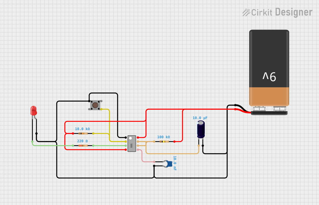
This circuit appears to be a simple timer or oscillator circuit utilizing a 555 timer IC. The 555 timer is configured with various external components including resistors, capacitors, and a pushbutton to control its operation. An LED is included to provide a visual indication of the output state. The circuit is powered by a 9V battery. There is no embedded code provided as there are no microcontrollers in this circuit.
Component List
555 Timer IC
- Description: A highly stable device for generating accurate time delays or oscillation.
- Pins: GND, TRIG, OUT, ~RESET, VCC, DIS, THR, CTRL
Pushbutton
- Description: A simple switch mechanism for control of a device or process.
- Pins: Pin 3 (out), Pin 4 (out), Pin 1 (in), Pin 2 (in)
LED: Two Pin (red)
- Description: A red light-emitting diode used as an indicator.
- Pins: cathode, anode
Resistor (10k Ohms)
- Description: A resistor with a resistance of 10,000 Ohms.
- Pins: pin1, pin2
Resistor (220 Ohms)
- Description: A resistor with a resistance of 220 Ohms.
- Pins: pin1, pin2
9V Battery
- Description: A standard 9V battery used as the power source.
- Pins: -, +
Ceramic Capacitor (10nF)
- Description: A ceramic capacitor with a capacitance of 10 nanofarads.
- Pins: pin0, pin1
Resistor (100k Ohms)
- Description: A resistor with a resistance of 100,000 Ohms.
- Pins: pin1, pin2
Electrolytic Capacitor (10uF)
- Description: An electrolytic capacitor with a capacitance of 10 microfarads.
- Pins: -, +
Wiring Details
555 Timer IC
- GND connected to Pushbutton (Pin 2 in), LED (anode), Ceramic Capacitor (pin1), Electrolytic Capacitor (+), and 9V Battery (-).
- TRIG connected to Pushbutton (Pin 3 out) and Resistor (10k Ohms, pin2).
- OUT connected to Resistor (220 Ohms, pin2).
- ~RESET connected to VCC.
- VCC connected to Resistor (10k Ohms, pin1), Resistor (100k Ohms, pin2), and 9V Battery (+).
- DIS connected to THR.
- THR connected to Resistor (100k Ohms, pin1) and Electrolytic Capacitor (-).
- CTRL connected to Ceramic Capacitor (pin0).
Pushbutton
- Pin 2 (in) connected to 555 Timer IC (GND).
- Pin 3 (out) connected to 555 Timer IC (TRIG).
LED: Two Pin (red)
- cathode connected to Resistor (220 Ohms, pin1).
- anode connected to 555 Timer IC (GND).
Resistor (10k Ohms)
- pin1 connected to 555 Timer IC (VCC).
- pin2 connected to 555 Timer IC (TRIG).
Resistor (220 Ohms)
- pin1 connected to LED (cathode).
- pin2 connected to 555 Timer IC (OUT).
9V Battery
- (-) connected to 555 Timer IC (GND).
- (+) connected to 555 Timer IC (VCC).
Ceramic Capacitor (10nF)
- pin0 connected to 555 Timer IC (CTRL).
- pin1 connected to 555 Timer IC (GND).
Resistor (100k Ohms)
- pin1 connected to 555 Timer IC (VCC).
- pin2 connected to 555 Timer IC (DIS).
Electrolytic Capacitor (10uF)
- (-) connected to 555 Timer IC (THR).
- (+) connected to 555 Timer IC (GND).
Documented Code
There is no embedded code provided for this circuit as it does not include any programmable components such as microcontrollers. The operation of the circuit is solely based on the configuration of the 555 timer and its associated passive components.