
Arduino UNO Controlled Bluetooth Robot with IR Sensor and LCD Feedback
View and Edit Project In Cirkit Designer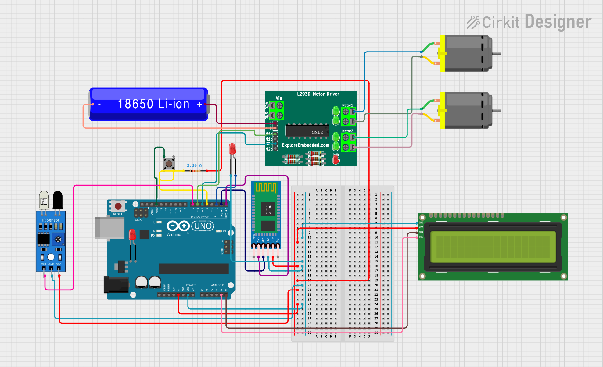
Circuit Documentation
Summary
This circuit integrates various components controlled by an Arduino UNO microcontroller to perform a range of functions. The circuit includes input devices like pushbuttons and an IR sensor, output devices such as LEDs and an I2C LCD screen, a communication module (HC-05 Bluetooth Module), and a motor driver (L293D) to control DC motors. The circuit is powered by an 18650 Li-ion battery. The Arduino UNO facilitates the interaction between these components, allowing for sensor data processing, motor control, and wireless communication.
Component List
- Arduino UNO: A microcontroller board based on the ATmega328P, with a variety of digital and analog I/O pins.
- HC-05 Bluetooth Module: A wireless communication module that enables Bluetooth connectivity.
- LED (Red): A simple light-emitting diode for indication purposes.
- Pushbutton: An input device used to trigger events.
- Resistor (2.2 Ohms): A component used to limit current or divide voltages in the circuit.
- L293D Motor Driver: A motor driver IC that allows DC motors to be driven in both directions.
- 18650 Li-ion Battery: A rechargeable battery providing power to the circuit.
- DC Motor: An electric motor that runs on direct current electricity.
- IR Sensor: An infrared sensor used for object detection or distance measurement.
- I2C LCD 16x2 Screen: A liquid crystal display capable of displaying 16 characters per line across 2 lines, with an I2C interface for communication.
Wiring Details
Arduino UNO
- GND: Connected to the ground pins of the I2C LCD screen, HC-05 Bluetooth Module, IR sensor, and one pin of the pushbutton.
- 5V: Supplies power to the I2C LCD screen, HC-05 Bluetooth Module, IR sensor, and one side of a resistor.
- A4 (SCL): Connected to the SCL pin of the I2C LCD screen for I2C communication.
- A5 (SDA): Connected to the SDA pin of the I2C LCD screen for I2C communication.
- D7: Receives the output signal from the IR sensor.
- D6: Controls one of the enable pins of the L293D motor driver.
- D5: Controls another enable pin of the L293D motor driver.
- D4: Connected to the other side of the resistor, which is also connected to a pushbutton.
- D2: Connected to the anode of a red LED.
- D1 (TX): Connected to the TXD pin of the HC-05 Bluetooth Module.
- D0 (RX): Connected to the RXD pin of the HC-05 Bluetooth Module.
HC-05 Bluetooth Module
- GND: Connected to the ground net.
- VCC: Connected to the 5V net.
- TXD: Connected to the D1 (TX) pin of the Arduino UNO.
- RXD: Connected to the D0 (RX) pin of the Arduino UNO.
LED (Red)
- Cathode: Connected to the ground net.
- Anode: Connected to the D2 pin of the Arduino UNO.
Pushbutton
- Pin 1 (in): Connected to the ground net.
- Pin 4 (out): Connected to the D4 pin of the Arduino UNO through a 2.2 Ohms resistor.
Resistor (2.2 Ohms)
- Pin1: Connected to the D4 pin of the Arduino UNO.
- Pin2: Connected to the 5V net and the pushbutton.
L293D Motor Driver
- Pin 5 & Pin 7: Controlled by the D6 and D5 pins of the Arduino UNO, respectively.
- Pin 10 & Pin 9: Connected to one of the DC motors.
- Pin 12 & Pin 11: Connected to the other DC motor.
- Pin 3: Connected to the positive terminal of the 18650 Li-ion Battery.
- Pin 4: Connected to the negative terminal of the 18650 Li-ion Battery.
18650 Li-ion Battery
- +: Connected to the pin 3 of the L293D motor driver.
- -: Connected to the pin 4 of the L293D motor driver.
DC Motor
- Pin 1 & Pin 2: Connected to the L293D motor driver.
IR Sensor
- Out: Connected to the D7 pin of the Arduino UNO.
- Gnd: Connected to the ground net.
- Vcc: Connected to the 5V net.
I2C LCD 16x2 Screen
- GND: Connected to the ground net.
- VCC (5V): Connected to the 5V net.
- SCL: Connected to the A4 pin of the Arduino UNO.
- SDA: Connected to the A5 pin of the Arduino UNO.
Documented Code
Arduino UNO Code (sketch.ino)
void setup() {
  // put your setup code here, to run once:

}

void loop() {
  // put your main code here, to run repeatedly:

}
Note: The provided code is a template and does not include specific functionality. It needs to be populated with the logic to control the components based on the circuit's requirements.