
Arduino UNO Controlled IR Sensor Array with Servo and LCD Feedback
View and Edit Project In Cirkit Designer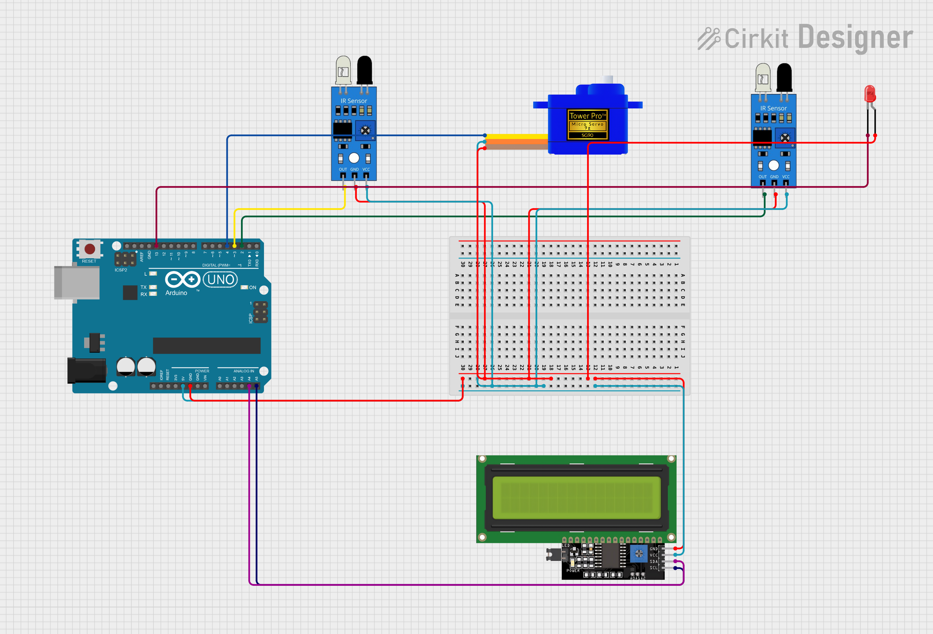
Circuit Documentation
Summary
This circuit integrates various components with an Arduino UNO microcontroller to perform a set of functions. The circuit includes input devices (IR sensors), output devices (LED, Servomotor, and an LCD Display), and is powered by the Arduino UNO's 5V output. The IR sensors are likely used for detecting objects or movements, the LED serves as an indicator, the Servomotor is used for actuation, and the LCD Display provides a user interface for displaying information. The Arduino UNO serves as the central processing unit, controlling the behavior of the other components based on the programmed logic.
Component List
Arduino UNO: A microcontroller board based on the ATmega328P. It has 14 digital input/output pins, 6 analog inputs, a USB connection, a power jack, an ICSP header, and a reset button.
LED (Red): A two-pin light-emitting diode that emits red light when powered.
IR Sensor: An infrared sensor capable of detecting infrared light, often used for proximity or motion detection.
Servomotor SG90: A small and lightweight servo motor capable of precise control. It can be positioned at various angles, typically between 0 and 180 degrees.
LCD Display 16x4 I2C: A 16x4 character LCD display that uses the I2C communication protocol for displaying text and characters.
Wiring Details
Arduino UNO
- GND: Connected to the ground pins of the LCD Display, LED, Servomotor, and both IR sensors.
- 5V: Provides power to the VCC pins of the LCD Display, Servomotor, and both IR sensors.
- A4 (SDA): Connected to the SDA pin of the LCD Display for I2C communication.
- A5 (SCL): Connected to the SCL pin of the LCD Display for I2C communication.
- D13: Connected to the cathode of the LED.
- D4: Connected to the SIG pin of the Servomotor for control signals.
- D3: Connected to the output of one IR sensor.
- D2: Connected to the output of the other IR sensor.
LED (Red)
- Anode: Connected to the common ground.
- Cathode: Connected to pin D13 of the Arduino UNO.
IR Sensors
- Out: Each IR sensor's output is connected to a digital pin on the Arduino UNO (D3 and D2).
- GND: Ground pins connected to the common ground.
- VCC: Power pins connected to the 5V output from the Arduino UNO.
Servomotor SG90
- SIG: Signal pin connected to pin D4 of the Arduino UNO.
- VCC: Power pin connected to the 5V output from the Arduino UNO.
- GND: Ground pin connected to the common ground.
LCD Display 16x4 I2C
- SCL: Serial Clock Line connected to pin A5 of the Arduino UNO.
- SDA: Serial Data Line connected to pin A4 of the Arduino UNO.
- VCC: Power pin connected to the 5V output from the Arduino UNO.
- GND: Ground pin connected to the common ground.
Documented Code
void setup() {
  // put your setup code here, to run once:

}

void loop() {
  // put your main code here, to run repeatedly:

}
The provided code is a template with empty setup() and loop() functions, which are the entry points for Arduino code. The setup() function is called once when the program starts and is used to initialize the environment. The loop() function is called repeatedly and contains the main logic of the program. Actual implementation details need to be filled in based on the desired behavior of the circuit.