
Circuit Documentation
Summary of the Circuit
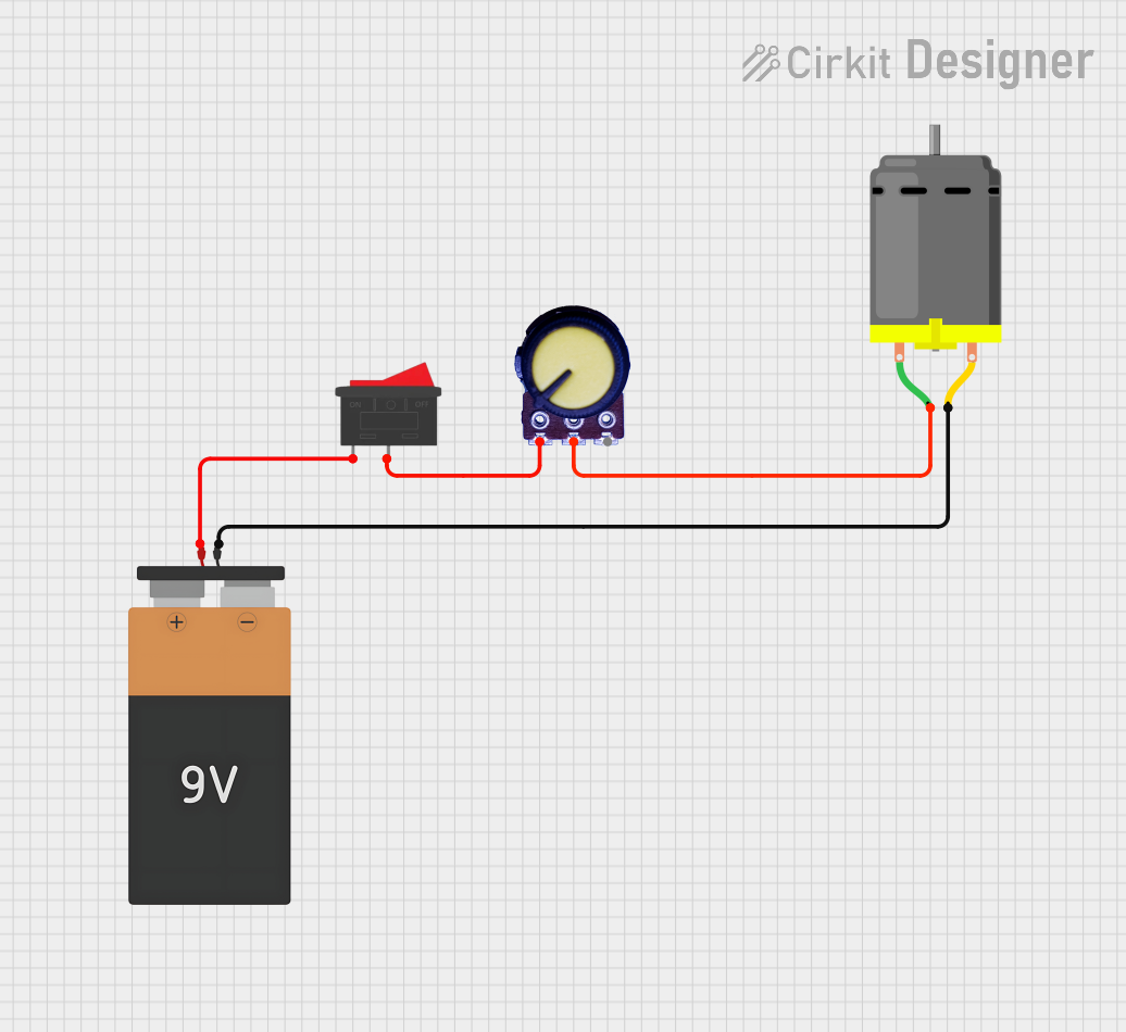
This circuit is designed to control a DC motor's speed using a potentiometer and a rocker switch to turn the motor on and off. The motor's speed is adjusted by varying the resistance of the potentiometer, which in turn changes the voltage applied to the motor. A 9V battery provides the power source for the circuit.
Component List
DC Motor
- Description: A standard DC motor that converts electrical energy into mechanical rotation.
- Pins:
- pin 1: Motor positive terminal
- pin 2: Motor negative terminal
Battery 9V
- Description: A 9V battery used as the power source for the circuit.
- Pins:
- VCC: Positive voltage supply
- GND: Ground reference
Rocker Switch
- Description: A rocker switch used to turn the motor on and off.
- Pins:
- 1: Input from the power source
- 2: Output to the load
Potentiometer
- Description: A variable resistor used to control the voltage applied to the DC motor.
- Pins:
- GND: Ground reference
- Output: Wiper output, which varies the voltage
- VCC: Positive voltage supply
Wiring Details
DC Motor
- pin 1: Connected to the wiper output (Output) of the Potentiometer.
- pin 2: Connected to the ground (GND) of the Battery 9V.
Battery 9V
- VCC: Connected to pin 1 of the Rocker Switch.
- GND: Connected to pin 2 of the DC Motor.
Rocker Switch
- 1: Connected to the VCC of the Battery 9V.
- 2: Connected to the GND pin of the Potentiometer.
Potentiometer
- GND: Connected to pin 2 of the Rocker Switch.
- Output: Connected to pin 1 of the DC Motor.
- VCC: Not connected in the provided net list.
Documented Code
There is no microcontroller or embedded code associated with this circuit as per the provided inputs. Therefore, this section is not applicable to the current documentation.