Cirkit Designer
Your all-in-one circuit design IDE
Home /
Project Documentation
Arduino-Based Flame Detection and Water Pump Activation System with Buzzer and LED Alerts
Circuit Documentation
Summary
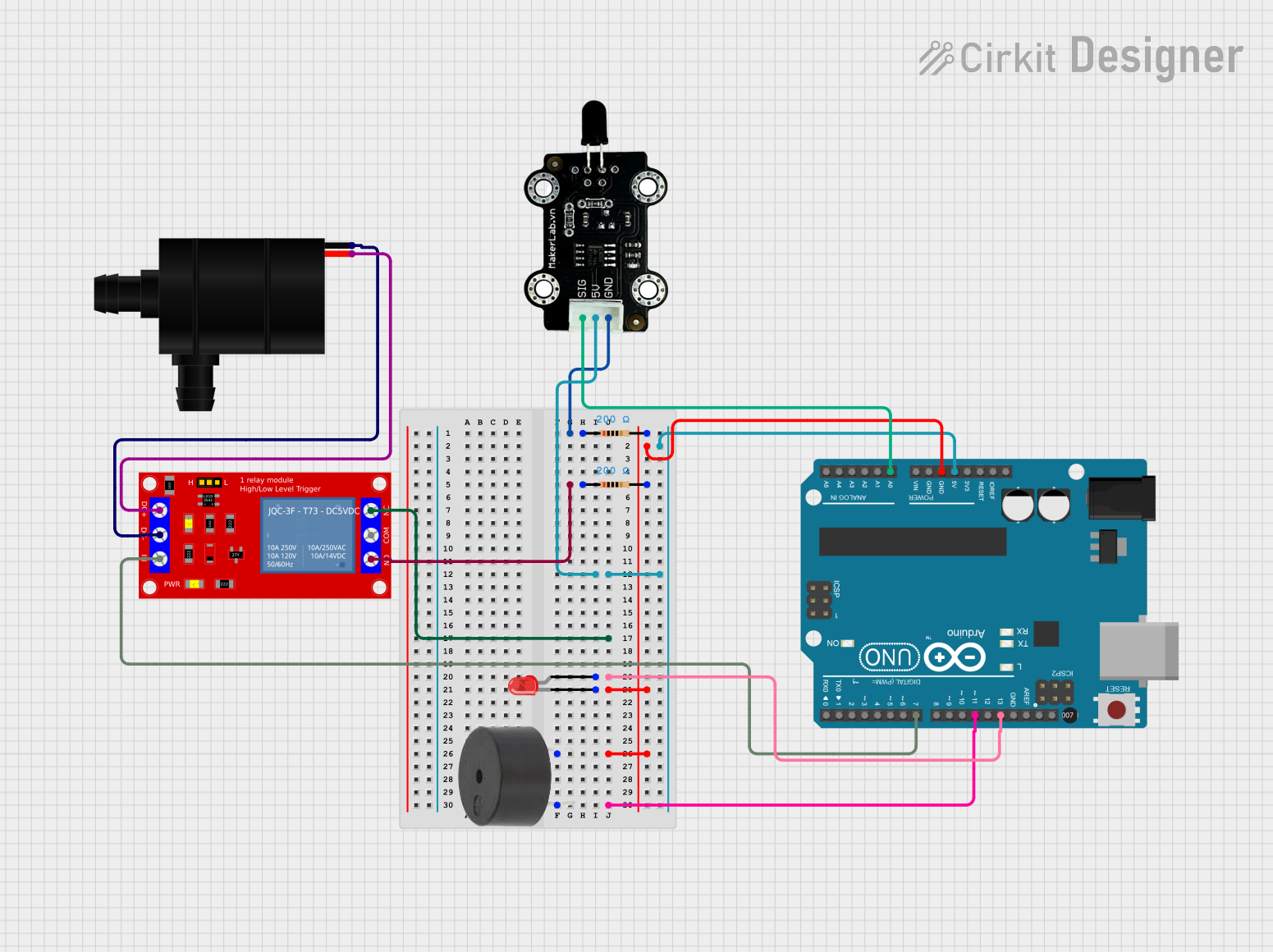
This circuit is designed to detect flames using an infrared flame sensor and activate a water pump via a relay module when a flame is detected. Additionally, an LED and a buzzer are used to provide visual and auditory alerts, respectively. The circuit is controlled by an Arduino UNO microcontroller.
Component List
MKE-S04 IR Infrared Flame Sensor
- Description: Detects infrared light emitted by flames.
- Pins: SIG, 5V, GND
1 Channel 5V Relay Module
- Description: Controls the water pump by switching it on or off.
- Pins: VCC+, VCC- (GND), IN, N.O., COM, N.C.
1N4007 Rectifier Diode
- Description: General-purpose rectifier diode.
- Pins: Cathode, Anode
Water Pump
- Description: Pumps water when activated.
- Pins: VCC, GND
Resistor (200 Ohms)
- Description: Limits current in the circuit.
- Pins: pin1, pin2
LED: Two Pin (red)
- Description: Provides visual alert.
- Pins: cathode, anode
Buzzer
- Description: Provides auditory alert.
- Pins: PIN, GND
Arduino UNO
- Description: Microcontroller that controls the entire circuit.
- Pins: UNUSED, IOREF, Reset, 3.3V, 5V, GND, Vin, A0, A1, A2, A3, A4, A5, SCL, SDA, AREF, D13, D12, D11, D10, D9, D8, D7, D6, D5, D4, D3, D2, D1, D0
Wiring Details
MKE-S04 IR Infrared Flame Sensor
- SIG connected to A0 on Arduino UNO
- 5V connected to 5V on Arduino UNO
- GND connected to pin1 of a 200 Ohm resistor
1 Channel 5V Relay Module
- VCC+ connected to VCC of Water Pump
- VCC- (GND) connected to GND of Water Pump
- IN connected to D7 on Arduino UNO
- N.O. connected to pin1 of a 200 Ohm resistor
- N.C. not connected
- COM not connected
1N4007 Rectifier Diode
- Cathode not connected
- Anode not connected
Water Pump
- VCC connected to VCC+ of Relay Module
- GND connected to VCC- (GND) of Relay Module
Resistor (200 Ohms)
- pin1 connected to GND of Flame Sensor
- pin2 connected to cathode of LED, GND of Buzzer, and GND on Arduino UNO
LED: Two Pin (red)
- anode connected to D13 on Arduino UNO
- cathode connected to pin2 of a 200 Ohm resistor
Buzzer
- PIN connected to D11 on Arduino UNO
- GND connected to pin2 of a 200 Ohm resistor
Arduino UNO
- 5V connected to 5V of Flame Sensor
- GND connected to pin2 of a 200 Ohm resistor
- A0 connected to SIG of Flame Sensor
- D7 connected to IN of Relay Module
- D11 connected to PIN of Buzzer
- D13 connected to anode of LED
Code Documentation
const int flameSensorPin = A0; // Flame sensor signal pin
const int relayPin = 7;        // Relay module trigger pin
const int buzzerPin = 11;      // Buzzer pin
const int ledPin = 13;         // LED pin

void setup() {
  // Initialize serial communication
  Serial.begin(9600);
  // Set pin modes
  pinMode(flameSensorPin, INPUT);
  pinMode(relayPin, OUTPUT);
  pinMode(buzzerPin, OUTPUT);
  pinMode(ledPin, OUTPUT);
  // Ensure the relay, buzzer, and LED are off initially
  digitalWrite(relayPin, LOW);
  digitalWrite(buzzerPin, LOW);
  digitalWrite(ledPin, LOW);
}

void loop() {
  // Read the flame sensor value
  int flameSensorValue = analogRead(flameSensorPin);
  // Print the sensor value to the serial monitor
  Serial.print("Flame Sensor Value: ");
  Serial.println(flameSensorValue);
  // Check if the flame sensor detects a fire
  if (flameSensorValue < 500) { // Adjust threshold as needed
    // Turn on the relay to activate the water pump
    digitalWrite(relayPin, HIGH);
    // Turn on the buzzer to alert
    digitalWrite(buzzerPin, HIGH);
    // Turn on the LED to alert
    digitalWrite(ledPin, HIGH);
  } else {
    // Turn off the relay to deactivate the water pump
    digitalWrite(relayPin, LOW);
    // Turn off the buzzer
    digitalWrite(buzzerPin, LOW);
    // Turn off the LED
    digitalWrite(ledPin, LOW);
  }
  // Small delay to avoid rapid switching
  delay(100);
}
This code initializes the pins for the flame sensor, relay, buzzer, and LED. It continuously reads the flame sensor value and activates the relay, buzzer, and LED if a flame is detected. The relay controls the water pump, turning it on when a flame is detected and off otherwise.