Remote-Controlled Drone with Motion Sensing Capabilities
Circuit Documentation
Summary of the Circuit
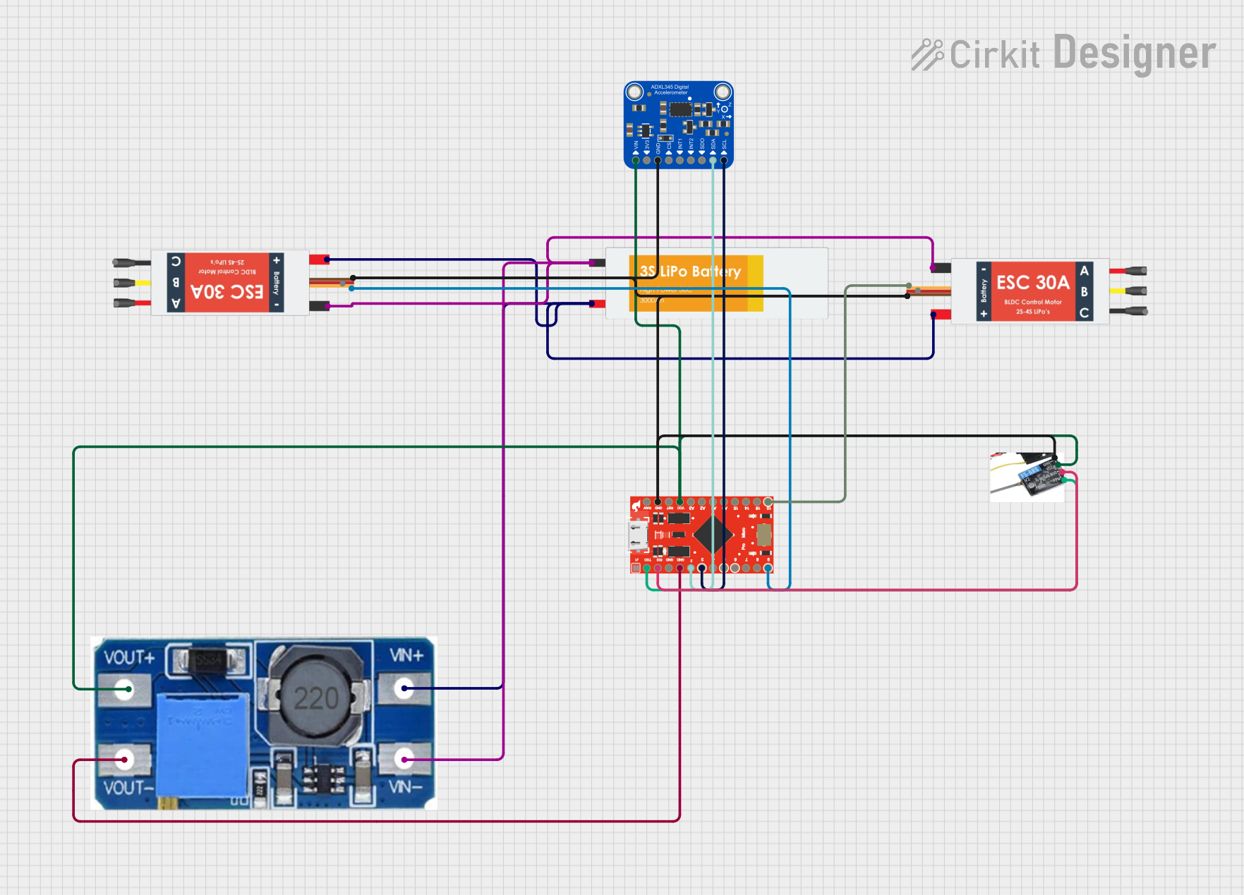
This circuit is designed to interface a microcontroller with a motion sensor, a receiver, electronic speed controllers (ESCs), and a power supply system. The microcontroller used is a SparkFun Pro Micro, which communicates with an Adafruit ADXL345 accelerometer and a flysky mini receiver. The ESCs are used to control motors (not detailed in the parts list), and the power supply system consists of a Lipo Battery and a Step Up Boost Power Converter to regulate the voltage. The circuit is designed to be powered by the Lipo Battery, with voltage regulation provided by the Step Up Boost Power Converter.
Component List
Adafruit ADXL345
- Accelerometer for measuring acceleration forces.
- Pins: VIN, 3.3V, GND, CS, INT1, INT2, SDO/ADDR, SDA/SDIO, SCL
Lipo Battery
- Power source for the circuit.
- Pins: VCC, GND
Electronic Speed Controller (ESC)
- Controls the speed of the motors.
- Pins: Battery VCC, Battery GND, Signal, 5v out, GND out, M1, M2, M3
flysky mini receiver
- Receives control signals from a remote transmitter.
- Pins: GND, BUS, ppm, vcc
Step Up Boost Power Converter, Adjustable Voltage Regulator
- Regulates and steps up the voltage from the battery.
- Pins: VOUT+, VOUT-, VIN+, VIN-
SparkFun Pro Micro
- Microcontroller that manages the logic and processing of the circuit.
- Pins: RAW, GND, RESET, VCC, A3, A2, A1, A0, SCK, MISO, MOSI, D10, D9, D8, D7, D6, D5, D4, D3, D2, RXI, TXO
Wiring Details
Adafruit ADXL345
- VIN connected to the VOUT+ of the Step Up Boost Power Converter.
- GND connected to the common ground net.
- SDA/SDIO connected to D2 of the SparkFun Pro Micro.
- SCL connected to D3 of the SparkFun Pro Micro.
Lipo Battery
- VCC connected to VIN+ of the Step Up Boost Power Converter and Battery VCC of both ESCs.
- GND connected to VIN- of the Step Up Boost Power Converter and Battery GND of both ESCs.
Electronic Speed Controller (ESC)
- Battery VCC connected to VCC of the Lipo Battery.
- Battery GND connected to GND of the Lipo Battery.
- Signal of one ESC connected to D10 of the SparkFun Pro Micro.
- Signal of the other ESC connected to D9 of the SparkFun Pro Micro.
- GND out connected to the common ground net.
flysky mini receiver
- vcc connected to VCC of the SparkFun Pro Micro.
- GND connected to the common ground net.
- BUS connected to RXI of the SparkFun Pro Micro.
- ppm connected to TXO of the SparkFun Pro Micro.
Step Up Boost Power Converter, Adjustable Voltage Regulator
- VOUT+ connected to VCC of the SparkFun Pro Micro, flysky mini receiver, and VIN of the Adafruit ADXL345.
- VOUT- connected to the common ground net.
- VIN+ connected to VCC of the Lipo Battery.
- VIN- connected to GND of the Lipo Battery.
SparkFun Pro Micro
- VCC connected to VOUT+ of the Step Up Boost Power Converter.
- GND connected to the common ground net.
- D2 connected to SDA/SDIO of the Adafruit ADXL345.
- D3 connected to SCL of the Adafruit ADXL345.
- D10 connected to Signal of one ESC.
- D9 connected to Signal of the other ESC.
- RXI connected to BUS of the flysky mini receiver.
- TXO connected to ppm of the flysky mini receiver.
Documented Code
No code has been provided for the microcontrollers in the circuit. The documentation of the code would typically include descriptions of the functions, algorithms, and communication protocols used by the microcontroller to interact with the other components in the circuit. Since no code is available, this section cannot be completed.