
Arduino Mega 2560 Controlled Motor System with Rotary Encoder Feedback
View and Edit Project In Cirkit Designer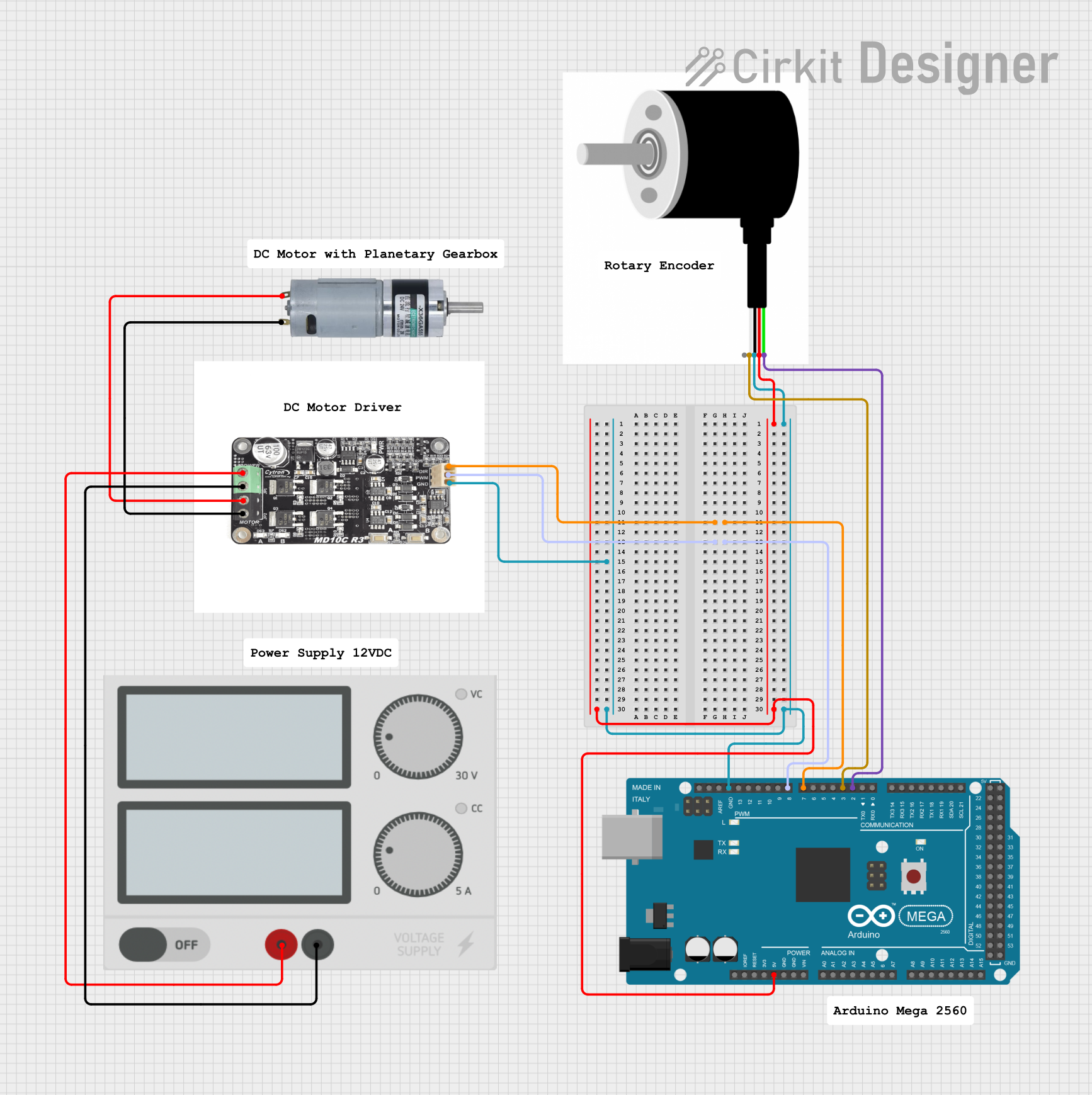
Circuit Documentation
Summary
This document provides a detailed overview of a circuit that includes a motor control system with a planetary gearbox motor, a rotary encoder for feedback, a motor driver, and an Arduino Mega 2560 microcontroller. The circuit is powered by an external power supply. The Arduino Mega 2560 is programmed to control the motor and read the encoder signals.
Component List
MRB Planetary Gearbox Motor
- Description: A motor with an integrated planetary gearbox.
- Pins: +, -
Rotary Encoder
- Description: A device that converts the angular position or motion of a shaft to an analog or digital signal.
- Pins: SHEILD, B PHASE, 0V, VCC, A PHASE
Motor Driver
- Description: A device that controls the direction and speed of the motor.
- Pins: Positive, Ground, Motor Phase A, Motor Phase B, Direction, PWM
Arduino Mega 2560
- Description: A microcontroller board based on the ATmega2560.
- Pins: IOREF, RESET, 3V3, 5V, GND, VIN, A0-A15, D0-D53, PWM pins, AREF, SDA, SCL
Power Supply
- Description: Provides the necessary power to the circuit.
- Pins: +, -
Comments
- Description: Placeholder components for documentation purposes.
- Pins: None
Wiring Details
MRB Planetary Gearbox Motor
- Pin + is connected to Motor Driver Motor Phase A.
- Pin - is connected to Motor Driver Motor Phase B.
Rotary Encoder
- Pin VCC is connected to Arduino Mega 2560 5V.
- Pin 0V is connected to Arduino Mega 2560 GND and Motor Driver Ground.
- Pin B PHASE is connected to Arduino Mega 2560 D3 PWM.
- Pin A PHASE is connected to Arduino Mega 2560 D2 PWM.
Motor Driver
- Pin Direction is connected to Arduino Mega 2560 D7 PWM.
- Pin PWM is connected to Arduino Mega 2560 D8 PWM.
- Pin Positive is connected to Power Supply +.
- Pin Ground is connected to Power Supply - and Rotary Encoder 0V.
Arduino Mega 2560
- Pin D7 PWM is connected to Motor Driver Direction.
- Pin D8 PWM is connected to Motor Driver PWM.
- Pin 5V is connected to Rotary Encoder VCC.
- Pin GND is connected to Rotary Encoder 0V and Motor Driver Ground.
- Pin D3 PWM is connected to Rotary Encoder B PHASE.
- Pin D2 PWM is connected to Rotary Encoder A PHASE.
Power Supply
- Pin + is connected to Motor Driver Positive.
- Pin - is connected to Motor Driver Ground.
Documented Code
Arduino Mega 2560 Code (sketch.ino)
void setup() {
  // put your setup code here, to run once:

}

void loop() {
  // put your main code here, to run repeatedly:

}
Documentation (documentation.txt)
This document provides a comprehensive overview of the circuit, including a summary, component list, wiring details, and documented code. The Arduino Mega 2560 is programmed to control the motor and read the encoder signals, ensuring precise motor control and feedback.