
Battery-Powered Arduino Pro Mini Servo Controller with INA3221 Monitoring
View and Edit Project In Cirkit Designer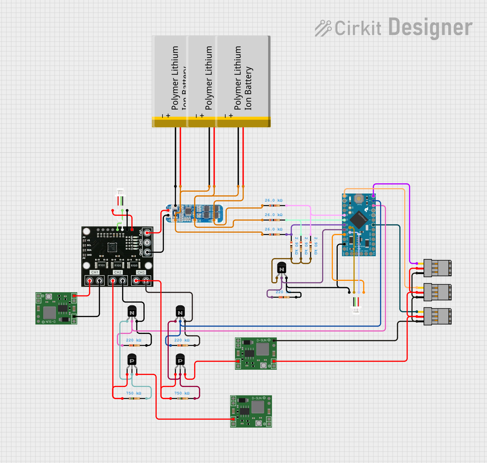
Circuit Documentation
Summary
This document provides a detailed overview of a circuit that includes an Arduino Pro Mini, a Battery Management System (BMS), multiple resistors, transistors, a power regulator, and other components. The circuit is designed to manage power distribution, control servos, and interface with sensors via I2C communication.
Component List
Arduino Pro Mini
- Description: A compact microcontroller board based on the ATmega328.
- Pins: DTR, TXO, RXI, VCC, GND, A4, A5, RAW, RESET, A3, A2, A1, A0, SCK, MISO, MOSI, D10, D9, D8, D7, D6, D5, D4, D3, D2
BMS
- Description: Battery Management System for managing lithium-ion batteries.
- Pins: B+, B2, B1, B-, P-, P+
Polymer Lithium Ion Battery - Generic
- Description: Generic lithium-ion battery.
- Pins: GND, VCC
Resistor (26k Ohms)
- Description: Resistor with a resistance of 26k Ohms.
- Pins: pin1, pin2
Resistor (2.9k Ohms)
- Description: Resistor with a resistance of 2.9k Ohms.
- Pins: pin1, pin2
Resistor (220k Ohms)
- Description: Resistor with a resistance of 220k Ohms.
- Pins: pin1, pin2
Resistor (750k Ohms)
- Description: Resistor with a resistance of 750k Ohms.
- Pins: pin1, pin2
NPN Transistor (EBC)
- Description: NPN transistor with emitter, base, and collector pins.
- Pins: emitter, base, collector
PNP Transistor (ECB)
- Description: PNP transistor with emitter, collector, and base pins.
- Pins: emitter, collector, base
INA3221
- Description: Triple-channel, high-side current and bus voltage monitor.
- Pins: TC, WAR, CRI, PV, SDA, SCL, GND, Vs, CH1, CH2, CH3, VPU, POW
JST SH1 I2C
- Description: I2C connector.
- Pins: VCC, SCL, SDA, GND
Servo Plug
- Description: Connector for servo motors.
- Pins: PWM, VCC, GND
MP1584EN Power Regulator Board
- Description: Power regulator board.
- Pins: IN-, IN+, OUT+, OUT-
Wiring Details
Arduino Pro Mini
- A4: Connected to SDA of JST SH1 I2C.
- A5: Connected to SCL of JST SH1 I2C.
- GND: Connected to GND of JST SH1 I2C, pin2 of a 220k Ohm resistor, collector of an NPN transistor.
- VCC: Connected to VCC of JST SH1 I2C.
- A3: Connected to base of an NPN transistor via pin1 of a 220k Ohm resistor.
- A2: Connected to pin1 of a 2.9k Ohm resistor, pin2 of a 26k Ohm resistor.
- A1: Connected to pin1 of a 2.9k Ohm resistor, pin2 of a 26k Ohm resistor.
- A0: Connected to pin1 of a 2.9k Ohm resistor, pin2 of a 26k Ohm resistor.
- D10: Connected to PWM of a Servo Plug.
- D9: Connected to PWM of a Servo Plug.
- D8: Connected to base of an NPN transistor via pin1 of a 220k Ohm resistor.
- D7: Connected to base of an NPN transistor via pin1 of a 220k Ohm resistor.
- D3: Connected to PWM of a Servo Plug.
BMS
- B+: Connected to VCC of a Polymer Lithium Ion Battery, pin1 of a 26k Ohm resistor.
- B2: Connected to GND of a Polymer Lithium Ion Battery, VCC of another Polymer Lithium Ion Battery, pin1 of a 26k Ohm resistor.
- B1: Connected to GND of a Polymer Lithium Ion Battery.
- B-: Connected to GND of a Polymer Lithium Ion Battery.
- P-: Connected to GND of INA3221.
- P+: Connected to VPU of INA3221.
Polymer Lithium Ion Battery - Generic
- VCC: Connected to B+ of BMS, pin1 of a 26k Ohm resistor.
- GND: Connected to GND of another Polymer Lithium Ion Battery, pin1 of a 26k Ohm resistor, B- of BMS.
Resistor (26k Ohms)
- pin1: Connected to VCC of a Polymer Lithium Ion Battery, B+ of BMS.
- pin2: Connected to pin1 of another 26k Ohm resistor, pin1 of a 2.9k Ohm resistor, pin1 of a 220k Ohm resistor.
Resistor (2.9k Ohms)
- pin1: Connected to A2, A1, A0 of Arduino Pro Mini.
- pin2: Connected to pin1 of another 2.9k Ohm resistor, pin1 of a 26k Ohm resistor.
Resistor (220k Ohms)
- pin1: Connected to base of an NPN transistor, A3 of Arduino Pro Mini.
- pin2: Connected to GND of Arduino Pro Mini, collector of an NPN transistor.
Resistor (750k Ohms)
- pin1: Connected to emitter of a PNP transistor, CH2 of INA3221.
- pin2: Connected to emitter of an NPN transistor, collector of a PNP transistor.
NPN Transistor (EBC)
- emitter: Connected to pin2 of a 2.9k Ohm resistor, pin2 of a 220k Ohm resistor.
- base: Connected to pin1 of a 220k Ohm resistor, A3 of Arduino Pro Mini.
- collector: Connected to GND of Arduino Pro Mini, pin2 of a 220k Ohm resistor.
PNP Transistor (ECB)
- emitter: Connected to pin1 of a 750k Ohm resistor, CH3 of INA3221.
- collector: Connected to pin2 of a 750k Ohm resistor, emitter of an NPN transistor.
- base: Connected to IN+ of MP1584EN Power Regulator Board.
INA3221
- SDA: Connected to SDA of JST SH1 I2C.
- SCL: Connected to SCL of JST SH1 I2C.
- GND: Connected to GND of JST SH1 I2C, P- of BMS.
- Vs: Connected to VCC of JST SH1 I2C.
- CH1: Connected to IN+ of MP1584EN Power Regulator Board.
- CH2: Connected to emitter of a PNP transistor, pin1 of a 750k Ohm resistor.
- CH3: Connected to emitter of a PNP transistor, pin1 of a 750k Ohm resistor.
- VPU: Connected to P+ of BMS.
JST SH1 I2C
- SDA: Connected to A4 of Arduino Pro Mini, SDA of INA3221.
- SCL: Connected to A5 of Arduino Pro Mini, SCL of INA3221.
- GND: Connected to GND of Arduino Pro Mini, GND of INA3221.
- VCC: Connected to VCC of Arduino Pro Mini, Vs of INA3221.
Servo Plug
- PWM: Connected to D10, D9, D3 of Arduino Pro Mini.
- VCC: Connected to OUT+ of MP1584EN Power Regulator Board.
- GND: Connected to OUT- of MP1584EN Power Regulator Board.
MP1584EN Power Regulator Board
- IN+: Connected to CH1 of INA3221.
- IN-: Connected to GND of INA3221.
- OUT+: Connected to VCC of Servo Plug.
- OUT-: Connected to GND of Servo Plug.
Documented Code
Arduino Pro Mini Code
void setup() {
  // put your setup code here, to run once:

}

void loop() {
  // put your main code here, to run repeatedly:

}
This code is a basic template for the Arduino Pro Mini. The setup function is used to initialize any settings or configurations, and the loop function contains the main code that runs repeatedly. Currently, both functions are empty and can be filled with the desired functionality for the circuit.