
Arduino Mega-Controlled Automation System with Stepper Motor, Servos, and Sensors
View and Edit Project In Cirkit Designer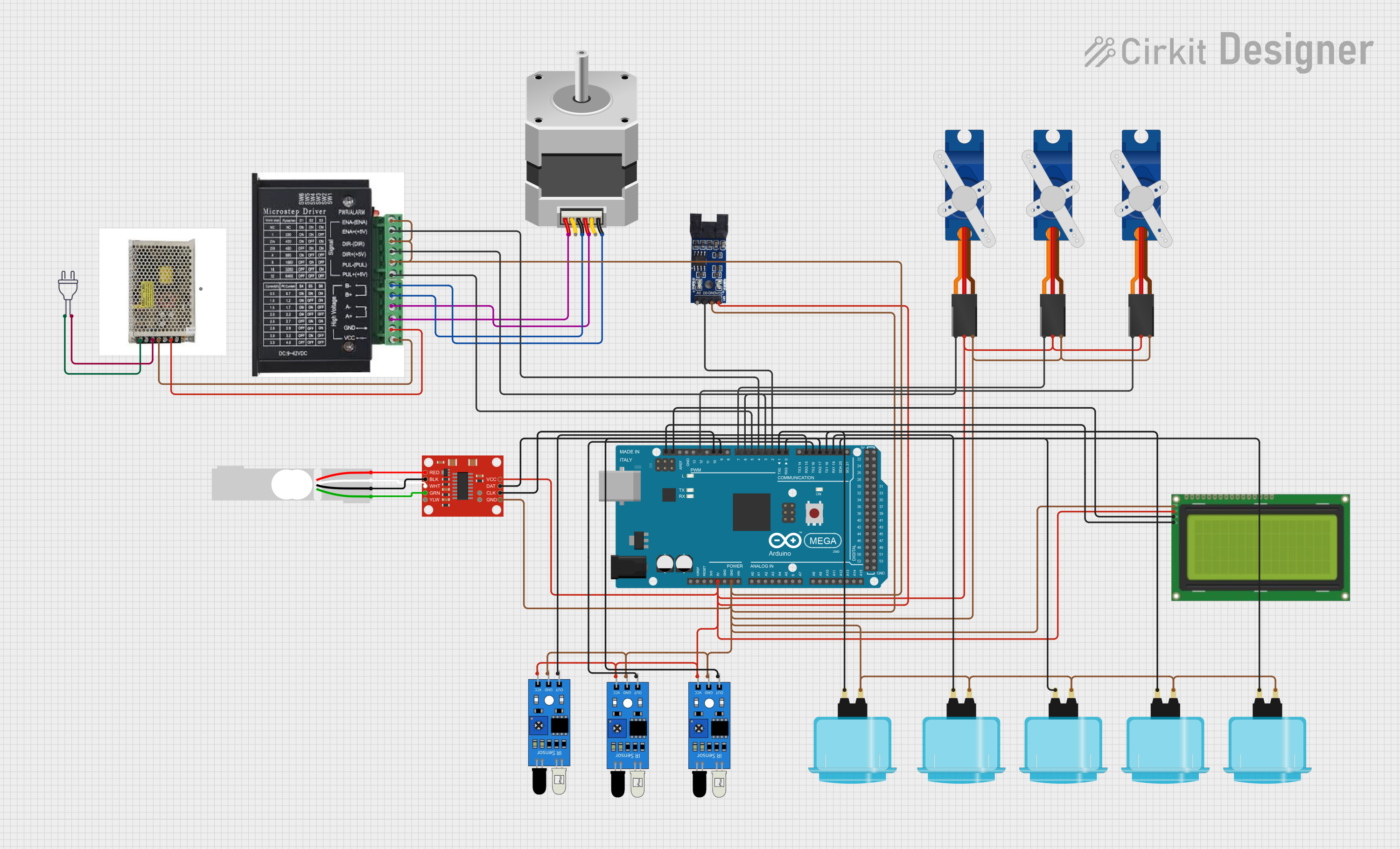
Circuit Documentation
Summary
This document provides a detailed overview of an electrical circuit designed to interface various components with an Arduino Mega 2560 microcontroller. The circuit includes a stepper motor with its driver, multiple IR sensors, servo motors, arcade buttons, an LCD display with I2C interface, a load cell with an amplifier, an optical encoder, and a power supply system. The Arduino Mega 2560 serves as the central processing unit, controlling the inputs and outputs to various peripherals.
Component List
Stepper Driver
- Description: A device that controls the operation of a stepper motor.
- Pins: ENA, ENA-, DIR-, DIR+, PUL-, PUL+, B-, B+, A-, A+, GND, VCC
Arcade Button (Blue)
- Description: A simple push-button switch used for user input.
- Pins: (Unnamed)
Tower Pro SG90 Servo
- Description: A small and lightweight servo motor for precise control.
- Pins: Signal, +5V, GND
IR Sensor
- Description: An infrared sensor used for detecting proximity or measuring distances.
- Pins: Out, GND, VCC
LCD 20x4 I2C
- Description: A 20x4 character LCD display with an I2C interface for displaying data.
- Pins: GND, 5V, SCA, SCL
Load Cell - Red/White/Black/Green
- Description: A transducer that converts force into an electrical signal.
- Pins: E+, A-, E-, A+
SparkFun Load Cell Amplifier - HX711
- Description: An amplifier for increasing the signal strength from a load cell.
- Pins: GND, CLK, DAT, VCC, YLW, GRN, WHT, BLK, RED, B-, B+
Stepper Motor (Unipolar)
- Description: A unipolar stepper motor for precise rotational movement.
- Pins: D, COMMON_2, B, C, COMMON_1, A
Power Supply 24 VDC
- Description: A power supply unit that provides 24V DC power.
- Pins: L, N, E, V+, V-
Power 220V
- Description: A power source that provides 220V AC power.
- Pins: Hot wire, Neutral wire
Optical Encoder Sensor Module
- Description: A sensor that provides feedback on the position of a rotating object.
- Pins: A0, D0, GND, VCC
Arduino Mega 2560
- Description: A microcontroller board based on the ATmega2560.
- Pins: Multiple digital and analog pins, power pins, and communication interfaces.
Wiring Details
Stepper Driver
- ENA, ENA-: Connected to Arduino for enable control.
- DIR-, DIR+: Connected to Arduino for direction control.
- PUL-, PUL+: Connected to Arduino for pulse control.
- B-, B+: Connected to Stepper Motor (Unipolar) pin D.
- A-, A+: Connected to Stepper Motor (Unipolar) pin C.
- GND: Connected to Power Supply 24 VDC V-.
- VCC: Connected to Power Supply 24 VDC V+.
Arcade Button (Blue)
- Unnamed Pin: Connected to various digital pins on the Arduino Mega 2560 for input detection.
Tower Pro SG90 Servo
- Signal: Connected to various PWM pins on the Arduino Mega 2560 for control signals.
- +5V: Connected to the 5V output on the Arduino Mega 2560.
- GND: Connected to the GND on the Arduino Mega 2560.
IR Sensor
- Out: Connected to various digital pins on the Arduino Mega 2560 for signal output.
- GND: Connected to the GND on the Arduino Mega 2560.
- VCC: Connected to the 5V output on the Arduino Mega 2560.
LCD 20x4 I2C
- GND: Connected to the GND on the Arduino Mega 2560.
- 5V: Connected to the 5V output on the Arduino Mega 2560.
- SCA: Connected to the SDA pin on the Arduino Mega 2560.
- SCL: Connected to the SCL pin on the Arduino Mega 2560.
Load Cell - Red/White/Black/Green
- E+: Connected to SparkFun Load Cell Amplifier - HX711 RED.
- A-: Connected to SparkFun Load Cell Amplifier - HX711 WHT.
- E-: Connected to SparkFun Load Cell Amplifier - HX711 BLK.
- A+: Connected to SparkFun Load Cell Amplifier - HX711 GRN.
SparkFun Load Cell Amplifier - HX711
- GND: Connected to the GND on the Arduino Mega 2560.
- CLK: Connected to digital pin D10 on the Arduino Mega 2560.
- DAT: Connected to digital pin D9 on the Arduino Mega 2560.
- VCC: Connected to the 5V output on the Arduino Mega 2560.
Stepper Motor (Unipolar)
- D, C: Connected to Stepper Driver B- and B+ respectively.
- B, A: Connected to Stepper Driver A- and A+ respectively.
Power Supply 24 VDC
- L: Connected to Power 220V hot wire.
- N: Connected to Power 220V neutral wire.
- E: Connected to Power 220V earth.
- V+: Connected to Stepper Driver VCC.
- V-: Connected to Stepper Driver GND.
Optical Encoder Sensor Module
- A0: Not connected in the provided net list.
- D0: Connected to digital pin D2 on the Arduino Mega 2560.
- GND: Connected to the GND on the Arduino Mega 2560.
- VCC: Connected to the 5V output on the Arduino Mega 2560.
Documented Code
Arduino Mega 2560 - sketch.ino
void setup() {
  // put your setup code here, to run once:

}

void loop() {
  // put your main code here, to run repeatedly:

}
Arduino Mega 2560 - documentation.txt
(No additional documentation provided)