Arduino UNO Controlled Line Following Robot with L298N Motor Driver and IR Sensors
Circuit Documentation
Summary of the Circuit
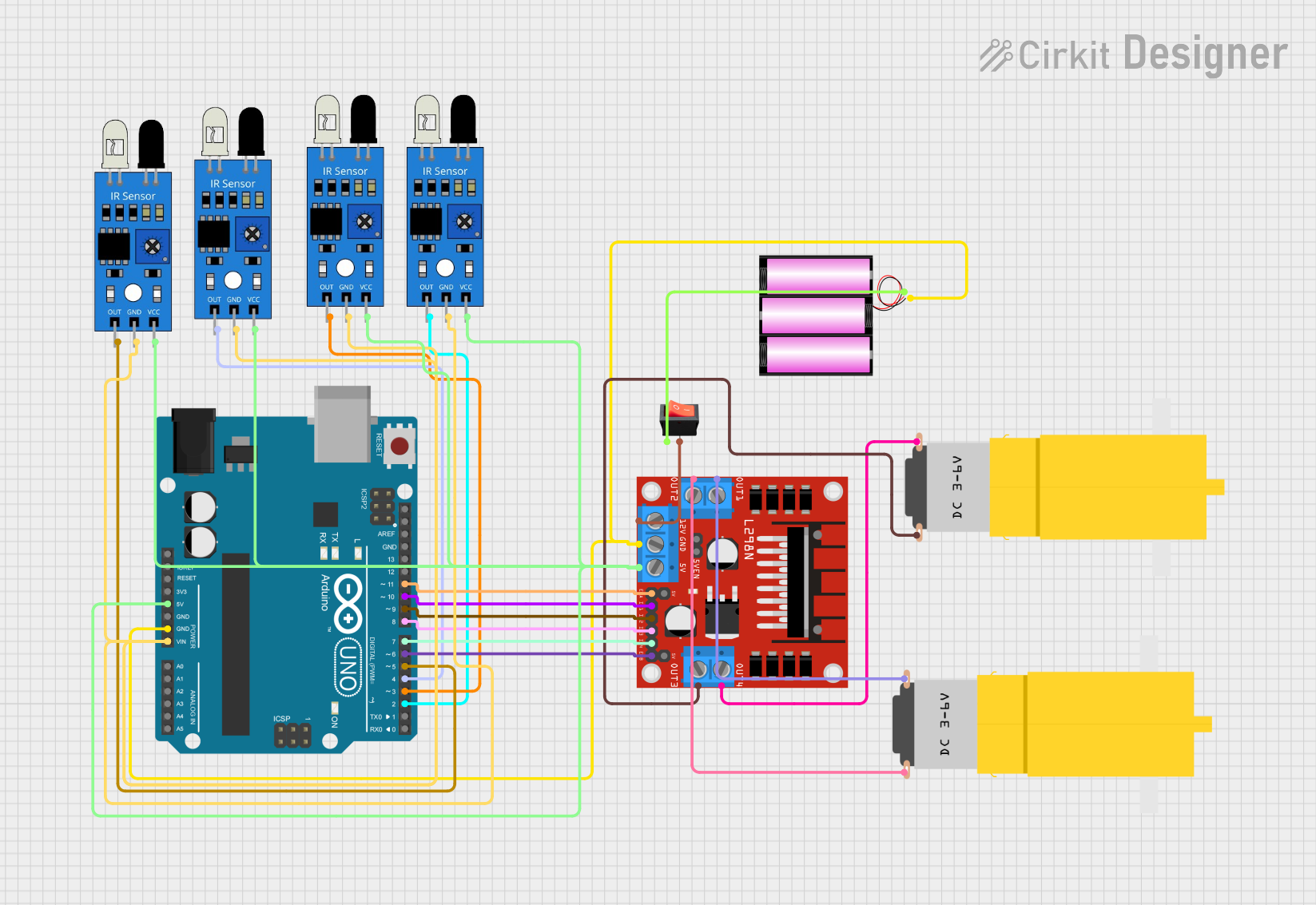
This circuit is designed to control a robot with two DC motors using an Arduino UNO as the main controller. The robot's path is determined by an array of four IR sensors that detect the presence of a line on the ground. The Arduino UNO reads the sensors' outputs and adjusts the motors' speeds using a PID control loop to keep the robot aligned with the line. The motors are driven by an L298N DC motor driver, which receives power from a 12V battery. A rocker switch is used to control the power supply to the motor driver.
Component List
Arduino UNO
- Microcontroller board based on the ATmega328P
- Used for reading IR sensor data and controlling the motor driver
IR Sensors (4x)
- Infrared sensors used for line detection
- Provide digital output to the Arduino UNO
L298N DC Motor Driver
- Dual H-bridge motor driver
- Controls the direction and speed of two DC motors
Battery 12V
- Provides power to the motor driver and the Arduino UNO
Motors (2x)
- DC motors used to drive the robot's wheels
Rocker Switch
- Controls the power supply from the battery to the motor driver
Wiring Details
Arduino UNO
5Vconnected to the5Vpower rail supplying the IR sensors and the L298N motor driverGNDconnected to the ground rail, which is also connected to the battery's negative terminal- Digital pins
D2toD11are used to interface with the IR sensors and the motor driver
IR Sensors
vccpins connected to the5Vpower railgndpins connected to the ground railoutpins connected to the Arduino UNO's digital pinsD2toD5
L298N DC Motor Driver
5Vconnected to the5Vpower railGNDconnected to the ground rail12Vconnected to the rocker switch's outputENAandENBconnected to Arduino UNO's digital pinsD11andD6for speed controlIN1toIN4connected to Arduino UNO's digital pinsD10toD7for direction controlOUT1toOUT4connected to the motors
Battery 12V
+connected to the rocker switch's input-connected to the ground rail
Motors
- One motor's
vccandGNDconnected toOUT1andOUT2of the motor driver - The other motor's
vccandGNDconnected toOUT3andOUT4of the motor driver
Rocker Switch
inputconnected to the battery's+terminaloutputconnected to the12Vinput of the motor driver
Documented Code
// Pin definitions for 4-channel IR sensor array
#define IR_SENSOR1 A5  // Left-most sensor
#define IR_SENSOR2 A4  // Left-middle sensor
#define IR_SENSOR3 A3  // Right-middle sensor
#define IR_SENSOR4 A2  // Right-most sensor

// Motor driver pin definitions
#define ENA 3  // Speed control for left motor
#define ENB 9  // Speed control for right motor
#define IN1 4  // Right motor backward
#define IN2 5  // Right motor forward
#define IN3 6  // Left motor backward
#define IN4 7  // Left motor forward

// Motor speed settings
int baseSpeed = 200;  // Base speed for motors
int maxSpeed = 255;   // Max motor speed

// PID control variables
float Kp = 65;            // Proportional constant
float Ki = 0.0084;        // Integral constant
float Kd = 7.9;           // Derivative constant
float previousError = 0;  // Store last error for derivative calculation
float integral = 0;       // Integral sum

int threshold = 400;  // Threshold for line detection (adjust as needed)

void setup() {
  // Motor driver pins
  pinMode(ENA, OUTPUT);
  pinMode(ENB, OUTPUT);
  pinMode(IN1, OUTPUT);
  pinMode(IN2, OUTPUT);
  pinMode(IN3, OUTPUT);
  pinMode(IN4, OUTPUT);

  // Begin serial monitor (optional for debugging)
  Serial.begin(9600);
}

void botLoop() {
  // Read analog values from sensors
  int sensor1 = analogRead(IR_SENSOR1);
  int sensor2 = analogRead(IR_SENSOR2);
  int sensor3 = analogRead(IR_SENSOR3);
  int sensor4 = analogRead(IR_SENSOR4);

  // Calculate position based on sensor readings
  int position = (sensor1 > threshold ? -3 : 0) + (sensor2 > threshold ? -1 : 0) +
                 (sensor3 > threshold ? 1 : 0) + (sensor4 > threshold ? 3 : 0);

  // Calculate error (0 means center, negative for left, positive for right)
  float error = position * -1;

  // PID calculations
  integral += error;                         // Accumulate the integral
  float derivative = error - previousError;  // Calculate the difference for derivative
  previousError = error;                     // Store current error for next loop

  // PID output to adjust motor speeds
  float correction = Kp * error + Ki * integral + Kd * derivative;

  // Calculate motor speeds with PID correction
  int leftSpeed = baseSpeed + correction;
  int rightSpeed = baseSpeed - correction;

  // Constrain speeds to motor limits
  leftSpeed = constrain(leftSpeed, (-3 * maxSpeed), maxSpeed);
  rightSpeed = constrain(rightSpeed, (-3 * maxSpeed), maxSpeed);

  // Print left motor speed only for Serial Plotter
  Serial.println(leftSpeed);

  // Move the motors
  moveForward(leftSpeed, rightSpeed);
}

void loop() {
  botLoop();
  delay(10);
}

void moveForward(int leftSpeed, int rightSpeed) {
  if (leftSpeed > 0) {
    digitalWrite(IN3, HIGH);   // Left motor forward
    digitalWrite(IN4, LOW);    // Left motor backward
  } else {
    digitalWrite(IN3, LOW);    // Left motor forward
    digitalWrite(IN4, HIGH);   // Left motor backward
  }

  if (rightSpeed > 0) {
    digitalWrite(IN1, LOW);    // Right motor forward
    digitalWrite(IN2, HIGH);   // Right motor backward
  } else {
    digitalWrite(IN1, HIGH);   // Right motor forward
    digitalWrite(IN2, LOW);    // Right motor backward
  }

  analogWrite(ENA, abs(rightSpeed));
  analogWrite(ENB, abs(leftSpeed));
}

void stopMotors() {
  digitalWrite(IN1, LOW);
  digitalWrite(IN2, LOW);
  digitalWrite(IN3, LOW);
  digitalWrite(IN4, LOW);
  analogWrite(ENA, 0);
  analogWrite(ENB, 0);
}
This code is responsible for reading the IR sensor values, calculating the position of the line, and adjusting the motor speeds accordingly using a PID control loop. The moveForward function controls the direction and speed of the motors, while the stopMotors function halts all motor activity. The botLoop function is the main loop that executes the PID control and motor movement logic.