
ESP32-CAM Ultrasonic Distance Sensor with QR Code Reader and LED Indicator
View and Edit Project In Cirkit Designer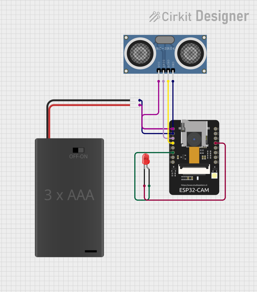
Circuit Documentation
Summary
This circuit involves an ESP32-CAM module connected to an HC-SR04 ultrasonic distance sensor and a red LED. The ESP32-CAM scans QR codes and controls the LED based on the distance measured by the ultrasonic sensor. The circuit is powered by a 3xAAA battery pack with a switch and JST connector.
Component List
ESP32-CAM
- Description: A microcontroller module with a built-in camera, Wi-Fi, and Bluetooth capabilities.
- Pins: 5V, GND, IO12, IO13, IO15, IO14, IO2, IO4, VOT, VOR, VCC, IO0, IO16, 3V3
3xAAA Battery Pack with Switch and JST
- Description: A battery pack that holds three AAA batteries and includes a switch and JST connector.
- Pins: POS, NEG
HC-SR04 Ultrasonic Distance Sensor (Wokwi Compatible)
- Description: An ultrasonic sensor used for measuring distance.
- Pins: VCC, TRIG, ECHO, GND
LED: Two Pin (red)
- Description: A standard red LED with two pins.
- Pins: cathode, anode
Wiring Details
ESP32-CAM
- 5V connected to POS of the 3xAAA Battery Pack
- GND connected to NEG of the 3xAAA Battery Pack
- IO12 connected to TRIG of the HC-SR04 Ultrasonic Distance Sensor
- IO13 connected to ECHO of the HC-SR04 Ultrasonic Distance Sensor
- IO14 connected to anode of the LED
- GND connected to cathode of the LED
3xAAA Battery Pack with Switch and JST
- POS connected to 5V of the ESP32-CAM
- POS connected to VCC of the HC-SR04 Ultrasonic Distance Sensor
- NEG connected to GND of the ESP32-CAM
- NEG connected to GND of the HC-SR04 Ultrasonic Distance Sensor
HC-SR04 Ultrasonic Distance Sensor (Wokwi Compatible)
- VCC connected to POS of the 3xAAA Battery Pack
- TRIG connected to IO12 of the ESP32-CAM
- ECHO connected to IO13 of the ESP32-CAM
- GND connected to NEG of the 3xAAA Battery Pack
LED: Two Pin (red)
- anode connected to IO14 of the ESP32-CAM
- cathode connected to GND of the ESP32-CAM
Code Documentation
/*
 * This Arduino Sketch is for an ESP32-CAM module connected to an HC-SR04
 * ultrasonic distance sensor and a red LED. The ESP32-CAM will scan QR codes
 * and control the LED based on the distance measured by the ultrasonic sensor.
 *
 * Connections:
 * - ESP32-CAM GND to Battery Pack NEG
 * - ESP32-CAM 5V to Battery Pack POS
 * - ESP32-CAM IO12 to HC-SR04 TRIG
 * - ESP32-CAM IO13 to HC-SR04 ECHO
 * - ESP32-CAM IO14 to LED anode
 * - ESP32-CAM GND to LED cathode
 * - HC-SR04 GND to Battery Pack NEG
 * - HC-SR04 VCC to Battery Pack POS
 */

#include <ESP32QRCodeReader.h>
#include <Ultrasonic.h>

// Define pin connections
#define TRIG_PIN 12
#define ECHO_PIN 13
#define LED_PIN 14

// Initialize ultrasonic sensor
Ultrasonic ultrasonic(TRIG_PIN, ECHO_PIN);

// Initialize QR code reader
ESP32QRCodeReader qrCodeReader;

void setup() {
  // Initialize serial communication
  Serial.begin(115200);

  // Initialize LED pin
  pinMode(LED_PIN, OUTPUT);
  digitalWrite(LED_PIN, LOW);

  // Initialize QR code reader
  qrCodeReader.begin();
}

void loop() {
  // Measure distance
  long distance = ultrasonic.read();
  Serial.print("Distance: ");
  Serial.print(distance);
  Serial.println(" cm");

  // Read QR code
  String qrCode = qrCodeReader.read();
  if (qrCode.length() > 0) {
    Serial.print("QR Code: ");
    Serial.println(qrCode);
  }

  // Control LED based on distance
  if (distance < 10) {
    digitalWrite(LED_PIN, HIGH);
  } else {
    digitalWrite(LED_PIN, LOW);
  }

  // Small delay to avoid flooding the serial monitor
  delay(500);
}
This code initializes the ESP32-CAM, sets up the ultrasonic sensor and QR code reader, and controls the LED based on the distance measured by the ultrasonic sensor. The QR code reader scans for QR codes and prints them to the serial monitor. The LED is turned on if the measured distance is less than 10 cm and turned off otherwise.