
Arduino UNO Controlled Traffic Light System with Touch Sensor
View and Edit Project In Cirkit Designer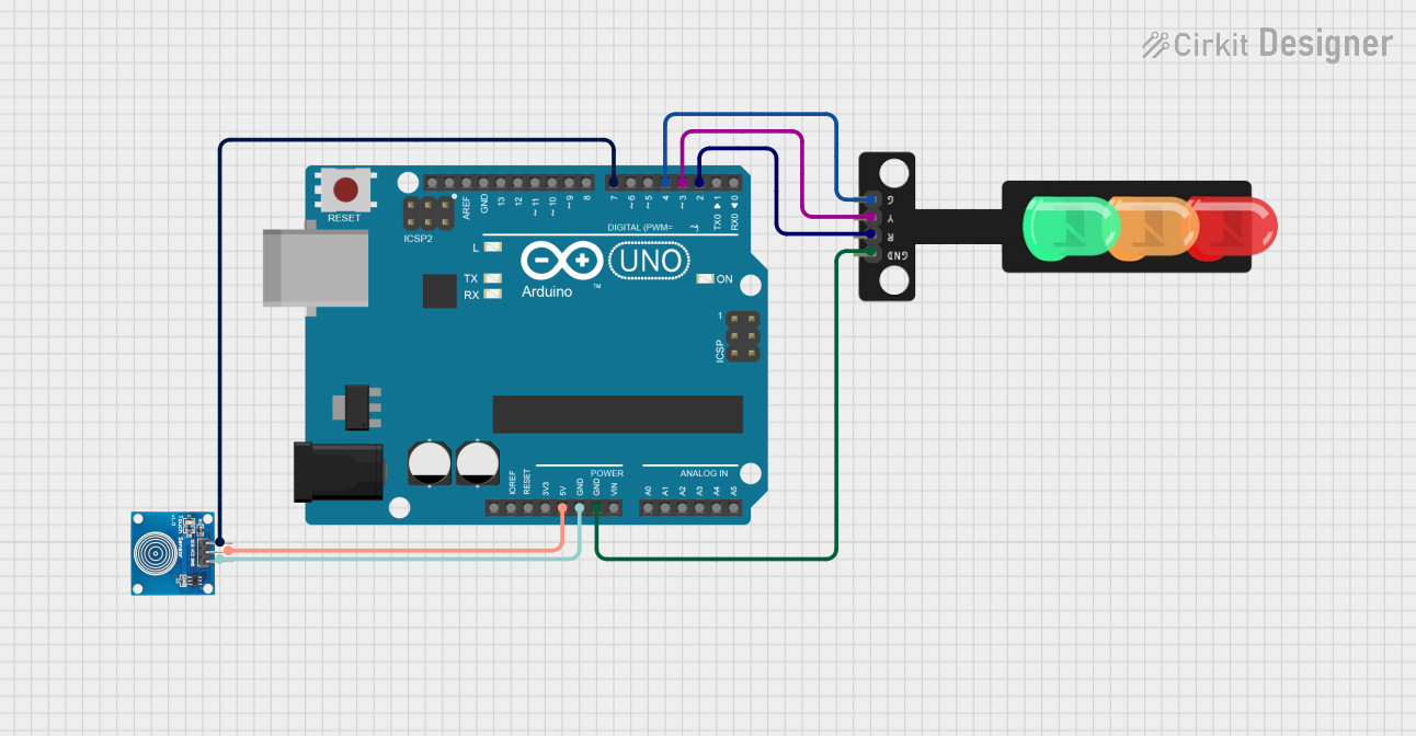
Traffic Light Control System Documentation
Summary
This document describes a traffic light control system designed using an Arduino UNO microcontroller, a touch sensor, and a traffic light module with red, yellow, and green LEDs. The system operates by cycling through the traffic light sequence (red, yellow, green, off) each time the touch sensor is activated. The Arduino UNO is programmed to detect touch sensor inputs and control the state of each LED accordingly.
Component List
Arduino UNO
- Description: A microcontroller board based on the ATmega328P.
- Purpose: Acts as the central processing unit for the traffic light control system, reading sensor inputs and controlling LED outputs.
- Pins: UNUSED, IOREF, Reset, 3.3V, 5V, GND, Vin, A0-A5, SCL, SDA, AREF, D0-D13.
Touch Sensor
- Description: A capacitive touch sensor module.
- Purpose: Provides user input to the system to cycle through the traffic light sequence.
- Pins: IO, VCC, GND.
Traffic Light Module
- Description: A module with three LEDs representing a traffic light.
- Purpose: Displays the traffic light sequence controlled by the Arduino UNO.
- Pins: Green, Yellow, Red, GND.
Wiring Details
Arduino UNO
- 5V connected to Touch Sensor VCC.
- GND connected to Touch Sensor GND and Traffic Light GND.
- D7 connected to Touch Sensor IO.
- D4 connected to Traffic Light Green.
- D3 connected to Traffic Light Yellow.
- D2 connected to Traffic Light Red.
Touch Sensor
- VCC connected to Arduino UNO 5V.
- GND connected to Arduino UNO GND.
- IO connected to Arduino UNO D7.
Traffic Light Module
- Green connected to Arduino UNO D4.
- Yellow connected to Arduino UNO D3.
- Red connected to Arduino UNO D2.
- GND connected to Arduino UNO GND.
Documented Code
/*
 * This Arduino sketch controls a traffic light system using a touch sensor.
 * When the touch sensor is pressed, the red LED turns on. On the next press,
 * the yellow LED turns on. On the next press, the green LED turns on. On the
 * next press, all LEDs turn off. This cycle repeats with each subsequent press.
 */

const int touchPin = 7; // Pin connected to the touch sensor
const int redPin = 2;   // Pin connected to the red LED
const int yellowPin = 3; // Pin connected to the yellow LED
const int greenPin = 4;  // Pin connected to the green LED

int touchState = 0; // Current state of the touch sensor
int lastTouchState = 0; // Previous state of the touch sensor
int ledState = 0; // State of the LEDs (0: all off, 1: red, 2: yellow, 3: green)

void setup() {
  pinMode(touchPin, INPUT);
  pinMode(redPin, OUTPUT);
  pinMode(yellowPin, OUTPUT);
  pinMode(greenPin, OUTPUT);
  digitalWrite(redPin, LOW);
  digitalWrite(yellowPin, LOW);
  digitalWrite(greenPin, LOW);
}

void loop() {
  touchState = digitalRead(touchPin);
  if (touchState == HIGH && lastTouchState == LOW) {
    ledState = (ledState + 1) % 4;
    updateLEDs();
  }
  lastTouchState = touchState;
}

void updateLEDs() {
  digitalWrite(redPin, ledState == 1 ? HIGH : LOW);
  digitalWrite(yellowPin, ledState == 2 ? HIGH : LOW);
  digitalWrite(greenPin, ledState == 3 ? HIGH : LOW);
}
Filename: sketch.ino
Description: The code defines the operation of the traffic light system. It sets up the pins connected to the touch sensor and LEDs as input and outputs, respectively. In the main loop, it reads the state of the touch sensor and cycles through the LED states. The updateLEDs function controls the LEDs based on the current state.