ESP32-Based Voice-Controlled Speaker
Circuit Documentation
Summary
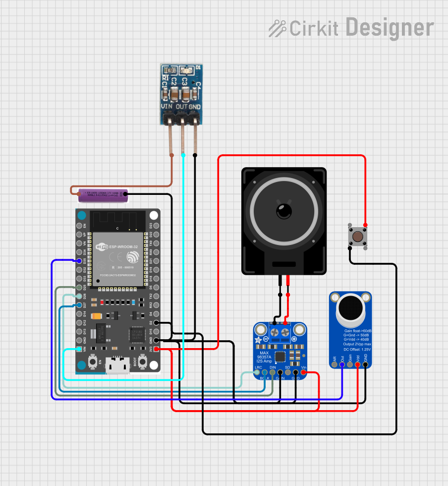
This circuit is designed to capture audio through an electret microphone, amplify the signal, and output the sound through a loudspeaker. It uses an ESP32 Devkit V1 microcontroller to process the audio signal and control the flow of data to an Adafruit MAX98357A I2S Class-D Mono Amp, which drives the loudspeaker. A pushbutton is included to provide user interaction, and a 3.7V battery powers the circuit through a 3.3V regulator to ensure a stable power supply for the components.
Component List
ESP32 Devkit V1
- Microcontroller with WiFi and Bluetooth capabilities.
- It has a variety of GPIO pins for interfacing with other components.
Loudspeaker
- An electroacoustic transducer used to produce sound.
Adafruit MAX98357A
- An I2S Class-D Mono Amplifier designed for use with digital audio signals.
Adafruit MAX9814 Electret Microphone Amplifier
- A microphone amplifier module with automatic gain control for consistent audio levels.
Pushbutton
- A simple switch mechanism for controlling some aspect of a machine or a process.
3.7V Battery
- A power source for the circuit, providing 3.7 volts.
3.3V Regulator
- A voltage regulator that ensures a constant 3.3V output from the varying input voltage.
Wiring Details
ESP32 Devkit V1
3V3connected to the 3.3V power rail.GNDconnected to the ground rail.D2connected to the pushbutton.D35connected to the output of the Adafruit MAX9814 Electret Microphone Amplifier.D25(DIN),D26(LRCLK),D27(BCLK) connected to the Adafruit MAX98357A for I2S audio data transmission.VINconnected to the 3.3V regulator output.
Loudspeaker
pin1connected to theVO-of the Adafruit MAX98357A.pin2connected to theVO+of the Adafruit MAX98357A.
Adafruit MAX98357A
VINconnected to the 3.3V power rail.GNDconnected to the ground rail.GAINconnected to the ground rail (setting gain to the default value).DINconnected toD25on the ESP32 Devkit V1.BCLKconnected toD27on the ESP32 Devkit V1.LRCLKconnected toD26on the ESP32 Devkit V1.VO+andVO-connected to the loudspeaker.
Adafruit MAX9814 Electret Microphone Amplifier
VDDconnected to the 3.3V power rail.GNDconnected to the ground rail.OUTPUTconnected toD35on the ESP32 Devkit V1.
Pushbutton
- One side connected to
D2on the ESP32 Devkit V1. - The other side connected to the ground rail.
3.7V Battery
+connected to theVinof the 3.3V regulator.-connected to the ground rail.
3.3V Regulator
Vinconnected to the+of the 3.7V battery.GNDconnected to the ground rail.OUTconnected to the 3.3V power rail.
Documented Code
There is no code provided for the microcontroller in this circuit. The ESP32 Devkit V1 would typically be programmed to handle the I2S communication with the Adafruit MAX98357A, process the audio signal from the Adafruit MAX9814 Electret Microphone Amplifier, and respond to the pushbutton input. The code would be responsible for initializing the I2S protocol, setting up GPIO pins, and implementing the logic for audio signal processing and user interaction. Since no code is provided, this section cannot be documented further.