Cirkit Designer
Your all-in-one circuit design IDE
Home /
Project Documentation
Arduino UNO-Based Color Sensor and Proximity Detection System with TCS3200 and Inductive Sensor
Circuit Documentation
Summary
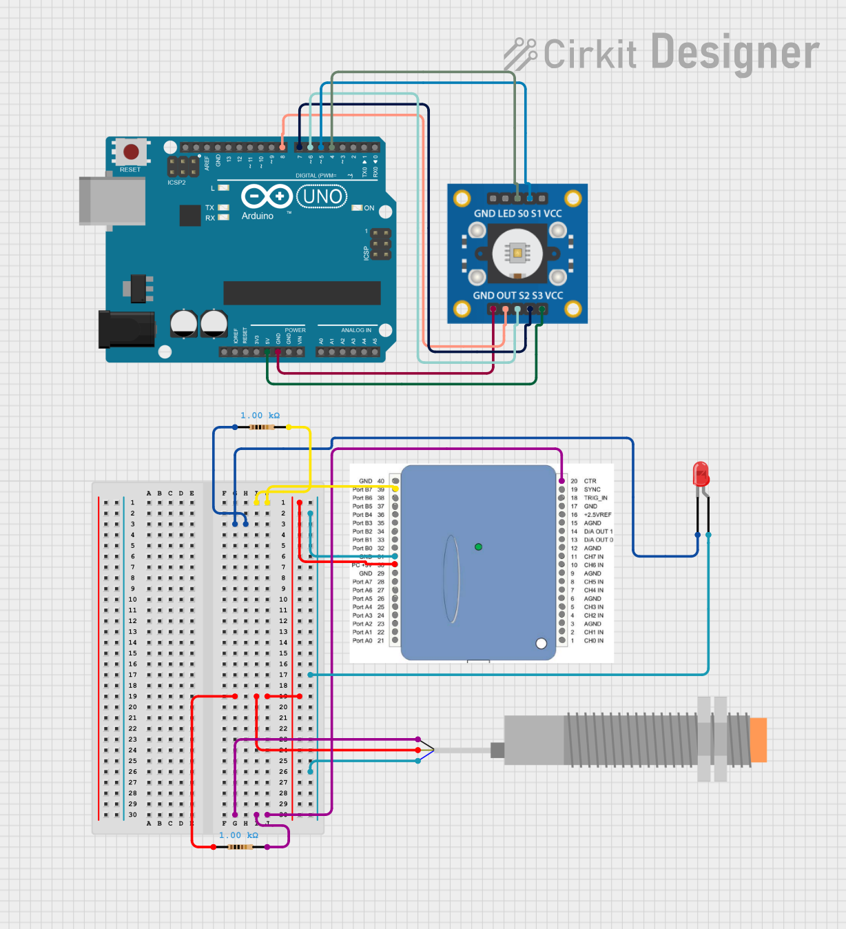
This document provides a detailed overview of a circuit that includes a TCS3200 color sensor, an LJ18A3-H-ZBX inductive proximity sensor, an Arduino UNO, resistors, and an LED. The circuit is designed to interface these components with the Arduino UNO for various sensing and output functionalities.
Component List
TCS3200 Color Sensor
- Description: A color sensor that can detect and measure the color of an object.
- Pins: GND, OUT, S2, S3, VCC, LED, S0, S1
LJ18A3-H-ZBX Inductive Proximity Sensor
- Description: An inductive sensor used to detect metallic objects without physical contact.
- Pins: VO (BLU), VI (BRN), SIG (BLK)
1408
- Description: A generic component used for grounding purposes.
- Pins: GND
Arduino UNO
- Description: A microcontroller board based on the ATmega328P, used for interfacing and controlling various components.
- Pins: UNUSED, IOREF, Reset, 3.3V, 5V, GND, Vin, A0, A1, A2, A3, A4, A5, SCL, SDA, AREF, D13, D12, D11, D10, D9, D8, D7, D6, D5, D4, D3, D2, D1, D0
Resistor (1k Ohms)
- Description: A resistor with a resistance of 1000 Ohms.
- Pins: pin1, pin2
LED: Two Pin (Red)
- Description: A red LED with two pins.
- Pins: cathode, anode
Wiring Details
TCS3200 Color Sensor
- GND: Connected to GND of Arduino UNO
- OUT: Connected to D8 of Arduino UNO
- S2: Connected to D6 of Arduino UNO
- S3: Connected to D7 of Arduino UNO
- VCC: Connected to 5V of Arduino UNO
- S0: Connected to D4 of Arduino UNO
- S1: Connected to D5 of Arduino UNO
LJ18A3-H-ZBX Inductive Proximity Sensor
- VI (BRN): Connected to pin1 of a 1k Ohm resistor
- SIG (BLK): Connected to pin2 of a 1k Ohm resistor
- VO (BLU): Connected to the anode of the red LED
1408
- GND: Connected to pin2 of a 1k Ohm resistor
Arduino UNO
- GND: Connected to GND of TCS3200 Color Sensor
- D8: Connected to OUT of TCS3200 Color Sensor
- D6: Connected to S2 of TCS3200 Color Sensor
- D7: Connected to S3 of TCS3200 Color Sensor
- 5V: Connected to VCC of TCS3200 Color Sensor
- D4: Connected to S0 of TCS3200 Color Sensor
- D5: Connected to S1 of TCS3200 Color Sensor
Resistor (1k Ohms)
- pin1: Connected to VI (BRN) of LJ18A3-H-ZBX Inductive Proximity Sensor
- pin2: Connected to GND of 1408
LED: Two Pin (Red)
- cathode: Connected to pin1 of a 1k Ohm resistor
- anode: Connected to VO (BLU) of LJ18A3-H-ZBX Inductive Proximity Sensor
Documented Code
Arduino UNO Code (sketch.ino)
void setup() {
  // put your setup code here, to run once:

}

void loop() {
  // put your main code here, to run repeatedly:

}
This code is a basic template for the Arduino UNO, with setup and loop functions ready for further development based on the specific requirements of the circuit.
This document provides a comprehensive overview of the circuit, including a summary, detailed component list, wiring details, and documented code. This should serve as a useful reference for understanding and replicating the circuit.