Cirkit Designer
Your all-in-one circuit design IDE
Home /
Project Documentation
Arduino UNO with DHT11 Temperature and Humidity Sensor
Circuit Documentation
Summary of the Circuit
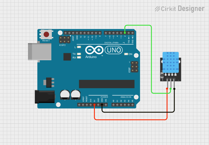
This circuit consists of an Arduino UNO microcontroller board interfaced with a KY-015 DHT11 temperature and humidity sensor. The Arduino UNO provides power to the DHT11 sensor and reads data from it through one of its digital pins. The purpose of this circuit is to measure the ambient temperature and humidity levels, which can be processed and utilized by the Arduino UNO for various applications such as environmental monitoring or climate control systems.
Component List
Arduino UNO
- Description: A microcontroller board based on the ATmega328P. It has 14 digital input/output pins, 6 analog inputs, a 16 MHz quartz crystal, a USB connection, a power jack, an ICSP header, and a reset button.
- Pins: UNUSED, IOREF, Reset, 3.3V, 5V, GND, Vin, A0-A5, SCL, SDA, AREF, D0-D13
KY-015 DHT11 Temperature and Humidity Sensor
- Description: A basic, ultra low-cost digital temperature and humidity sensor. It uses a capacitive humidity sensor and a thermistor to measure the surrounding air and outputs a digital signal on the data pin.
- Pins: 5V, S, GND
Wiring Details
Arduino UNO
- 5V: Provides power to the DHT11 sensor.
- D2: Reads data from the DHT11 sensor.
- GND: Common ground with the DHT11 sensor.
KY-015 DHT11 Temperature and Humidity Sensor
- 5V: Receives power from the Arduino UNO's 5V pin.
- S: Data pin connected to the Arduino UNO's D2 pin.
- GND: Connected to the Arduino UNO's GND pin.
Documented Code
Arduino UNO Code (sketch.ino)
void setup() {
  // put your setup code here, to run once:

}

void loop() {
  // put your main code here, to run repeatedly:

}
Additional Notes
- The provided code is a template and does not contain the implementation for interacting with the DHT11 sensor. The user is expected to include the necessary libraries and write the code to initialize the sensor, read data from it, and process the data accordingly.
- The
documentation.txtfile is empty and does not contain any additional information about the code or the circuit.