
Circuit Documentation
Summary
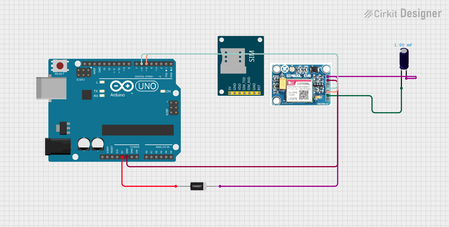
This circuit involves an Arduino UNO microcontroller interfacing with a SIM 800L V2.0 GSM module. The circuit is designed to send SMS messages using the GSM module. Additionally, a 1N4007 rectifier diode and an electrolytic capacitor are used for power regulation and filtering.
Component List
Arduino UNO
- Description: A microcontroller board based on the ATmega328P.
- Pins: UNUSED, IOREF, Reset, 3.3V, 5V, GND, Vin, A0, A1, A2, A3, A4, A5, SCL, SDA, AREF, D13, D12, D11, D10, D9, D8, D7, D6, D5, D4, D3, D2, D1, D0
SIM 800L V2.0 GSM
- Description: A GSM module for sending and receiving SMS, making and receiving voice calls.
- Pins: SIM_TXD, VDD, SIM.RXD, 5V/4V, GND, RST
1N4007 Rectifier Diode
- Description: A general-purpose silicon rectifier diode.
- Pins: Cathode, Anode
Electrolytic Capacitor
- Description: A capacitor used for filtering and power regulation.
- Pins: -, +
- Properties:
- Capacitance: 0.001 Farads
Wiring Details
Arduino UNO
- 5V connected to Anode of 1N4007 Rectifier Diode
- GND connected to GND of SIM 800L V2.0 GSM
- D6 connected to SIM_TXD of SIM 800L V2.0 GSM
- D5 connected to SIM.RXD of SIM 800L V2.0 GSM
SIM 800L V2.0 GSM
- GND connected to GND of Arduino UNO
- SIM_TXD connected to D6 of Arduino UNO
- SIM.RXD connected to D5 of Arduino UNO
- 5V/4V connected to Cathode of 1N4007 Rectifier Diode
- GND connected to - of Electrolytic Capacitor
1N4007 Rectifier Diode
- Anode connected to 5V of Arduino UNO
- Cathode connected to + of Electrolytic Capacitor
- Cathode connected to 5V/4V of SIM 800L V2.0 GSM
Electrolytic Capacitor
- + connected to Cathode of 1N4007 Rectifier Diode
- - connected to GND of SIM 800L V2.0 GSM
Code Documentation
Arduino UNO Code
#include <SoftwareSerial.h>

// Define the pins for SoftwareSerial
#define SIM800_TX_PIN 6
#define SIM800_RX_PIN 5

// Create a SoftwareSerial object
SoftwareSerial sim800(SIM800_TX_PIN, SIM800_RX_PIN);

// Your phone number and the message to send
const char phoneNumber[] = "+918329426293"; // Replace with your phone number
const char message[] = "Hello, this is a test message from SIM800 module.";

void setup() {
  // Initialize hardware serial for debugging
  Serial.begin(9600);
  // Initialize software serial for SIM800 communication
  sim800.begin(9600);

  // Wait for the SIM800 to initialize
  delay(2000); // Increased delay for initialization

  // Send an AT command to check if the SIM800 is responding
  Serial.println("Sending AT command...");
  sim800.println("AT");
  delay(1000);

  // Read the response from the SIM800
  if (sim800.available()) {
    Serial.println("SIM800 response:");
    while (sim800.available()) {
      Serial.write(sim800.read());
    }
  } else {
    Serial.println("No response from SIM800");
  }

  // Send SMS
  sendSMS(phoneNumber, message);
}

void loop() {
  // Main code to run repeatedly
  if (sim800.available()) {
    Serial.write(sim800.read());
  }
  if (Serial.available()) {
    sim800.write(Serial.read());
  }
}

void sendSMS(const char* number, const char* text) {
  // Set SMS mode to text
  sim800.println("AT+CMGF=1");
  delay(1000);
  // Send the SMS command
  sim800.print("AT+CMGS=\"");
  sim800.print(number);
  sim800.println("\"");
  delay(1000);
  // Send the SMS text
  sim800.println(text);
  delay(1000);
  // End the SMS with a Ctrl+Z character
  sim800.write(26);
  delay(1000);

  // Read the response from the SIM800
  if (sim800.available()) {
    Serial.println("SMS response:");
    while (sim800.available()) {
      Serial.write(sim800.read());
    }
  } else {
    Serial.println("No response from SIM800 after sending SMS");
  }
}
This code initializes the Arduino UNO to communicate with the SIM 800L V2.0 GSM module using SoftwareSerial. It sends an SMS message to a predefined phone number. The code includes functions to initialize the GSM module, send AT commands, and handle responses.