
Arduino-Controlled Motor and Actuator System with Soil Sensing and RS-485 Communication
View and Edit Project In Cirkit Designer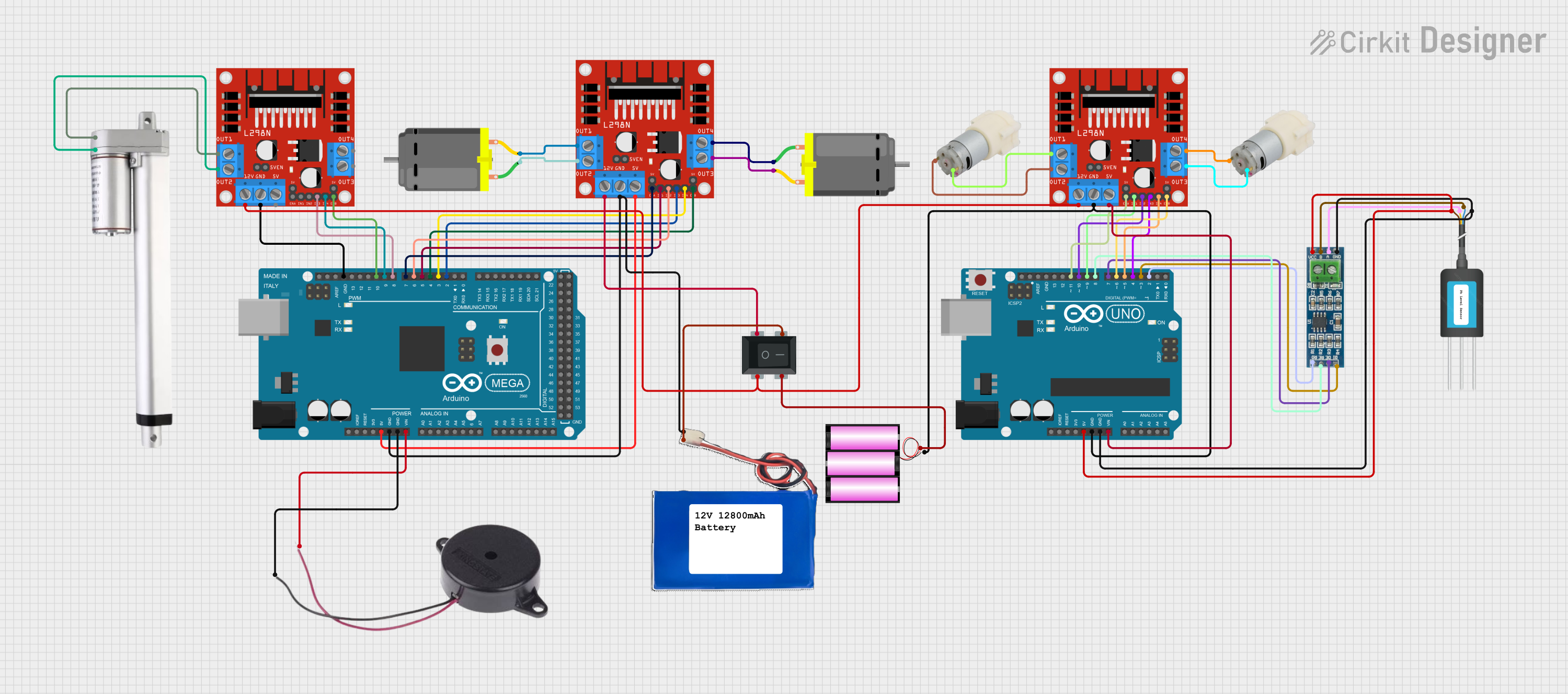
Circuit Documentation
Summary
The circuit in question is designed to control various DC motors, actuators, and a water pump using two microcontrollers, namely an Arduino UNO and an Arduino Mega 2560. The circuit also includes motor drivers (L298N), a rocker switch, a buzzer, a soil sensor (NPK Soil Sensor), an RS-485 module for communication, and power sources (a 12V battery and a Lithium-ion battery). The circuit's primary function is to drive motors and actuators, read sensor data, and communicate via RS-485.
Component List
Microcontrollers
- Arduino UNO: A microcontroller board based on the ATmega328P, featuring digital and analog I/O pins.
- Arduino Mega 2560: A microcontroller board based on the ATmega2560, with extended I/O pins and capabilities compared to the UNO.
Motor Drivers
- L298N DC Motor Driver: A high-power motor driver capable of driving up to two DC motors or one stepper motor.
Motors and Actuators
- DC Motor: An electric motor that runs on direct current (DC) electricity.
- Actuator Motor: A type of motor used to create mechanical movement by converting electrical energy into kinetic energy.
- Water Pump 12V: A pump that operates on 12V DC, used for moving water.
Sensors
- NPK Soil Sensor: A sensor used to measure the nutrient content in the soil.
Communication Modules
- RS-485 Module: A module used for long-distance communication in industrial environments.
Switches
- Rocker Switch 4 Pin: A switch used to control the power supply to the circuit components.
Power Sources
- Battery 12V: A 12V battery used to power the circuit.
- Lithium-ion Battery 10000mAh: A rechargeable battery providing a nominal voltage of 11.1V.
Other Components
- Buzzer: An electronic device that emits a sound when a voltage is applied.
Wiring Details
Arduino UNO
- 5V connected to NPK Soil Sensor (12V DC) and RS-485 Module (VCC)
- GND connected to NPK Soil Sensor (GND) and RS-485 Module (GND)
- Vin connected to L298N DC Motor Driver (5V)
- Digital Pins (D2-D11) connected to RS-485 Module (RO, DI, RE, DE) and L298N DC Motor Driver (IN1, IN2, IN3, IN4, ENA, ENB)
Arduino Mega 2560
- 5V connected to L298N DC Motor Driver (5V)
- GND connected to L298N DC Motor Driver (GND), Buzzer (NEGATIVE), and Lithium-ion Battery (GND)
- VIN connected to Buzzer (POSITIVE)
- PWM Pins (D2-D10) connected to L298N DC Motor Driver (IN1, IN2, IN3, IN4, ENA, ENB)
L298N DC Motor Driver
- OUT1 and OUT2 connected to DC Motors
- OUT3 and OUT4 connected to Actuator Motor and Water Pumps
- 12V connected to Rocker Switch (1)
- 5V, ENA, ENB, IN1, IN2, IN3, IN4 connected to respective Arduino pins as per the net list
- GND connected to the ground of the power sources and Arduino boards
Rocker Switch 4 Pin
- Pin 1 connected to L298N DC Motor Driver (12V)
- Pin 2 connected to L298N DC Motor Drivers (12V)
- Pin 3 connected to Lithium-ion Battery (11.1V)
- Pin 4 connected to Battery 12V (+)
DC Motor
- Pin 1 and Pin 2 connected to L298N DC Motor Driver (OUT1, OUT2)
Actuator Motor
- 12 V and Ground connected to L298N DC Motor Driver (OUT1, OUT2)
Water Pump 12V
-
- and - connected to L298N DC Motor Driver (OUT1, OUT2)
NPK Soil Sensor
- 12V DC connected to Arduino UNO (5V)
- A and B connected to RS-485 Module (A, B)
- GND connected to Arduino UNO (GND)
RS-485 Module
- VCC connected to Arduino UNO (5V)
- A and B connected to NPK Soil Sensor (A, B)
- GND connected to Arduino UNO (GND)
- RO, RE, DE, DI connected to respective Arduino UNO pins as per the net list
Buzzer
- POSITIVE connected to Arduino Mega 2560 (VIN)
- NEGATIVE connected to Arduino Mega 2560 (GND)
Documented Code
Arduino UNO Code (Instance ID: 32836fdd-f7ad-464a-ac28-786d70e79e1a)
void setup() {
  // put your setup code here, to run once:

}

void loop() {
  // put your main code here, to run repeatedly:

}
Arduino Mega 2560 Code (Instance ID: 90dce51d-7011-43d8-8ed6-206b29c93f2a)
void setup() {
  // put your setup code here, to run once:

}

void loop() {
  // put your main code here, to run repeatedly:

}
This documentation provides an overview of the circuit's components, their connections, and the initial code for the microcontrollers. Further development of the code is required to implement the circuit's intended functionality.