
Arduino Mega 2560-Based Keypad and LCD Interface with Adjustable Contrast
View and Edit Project In Cirkit Designer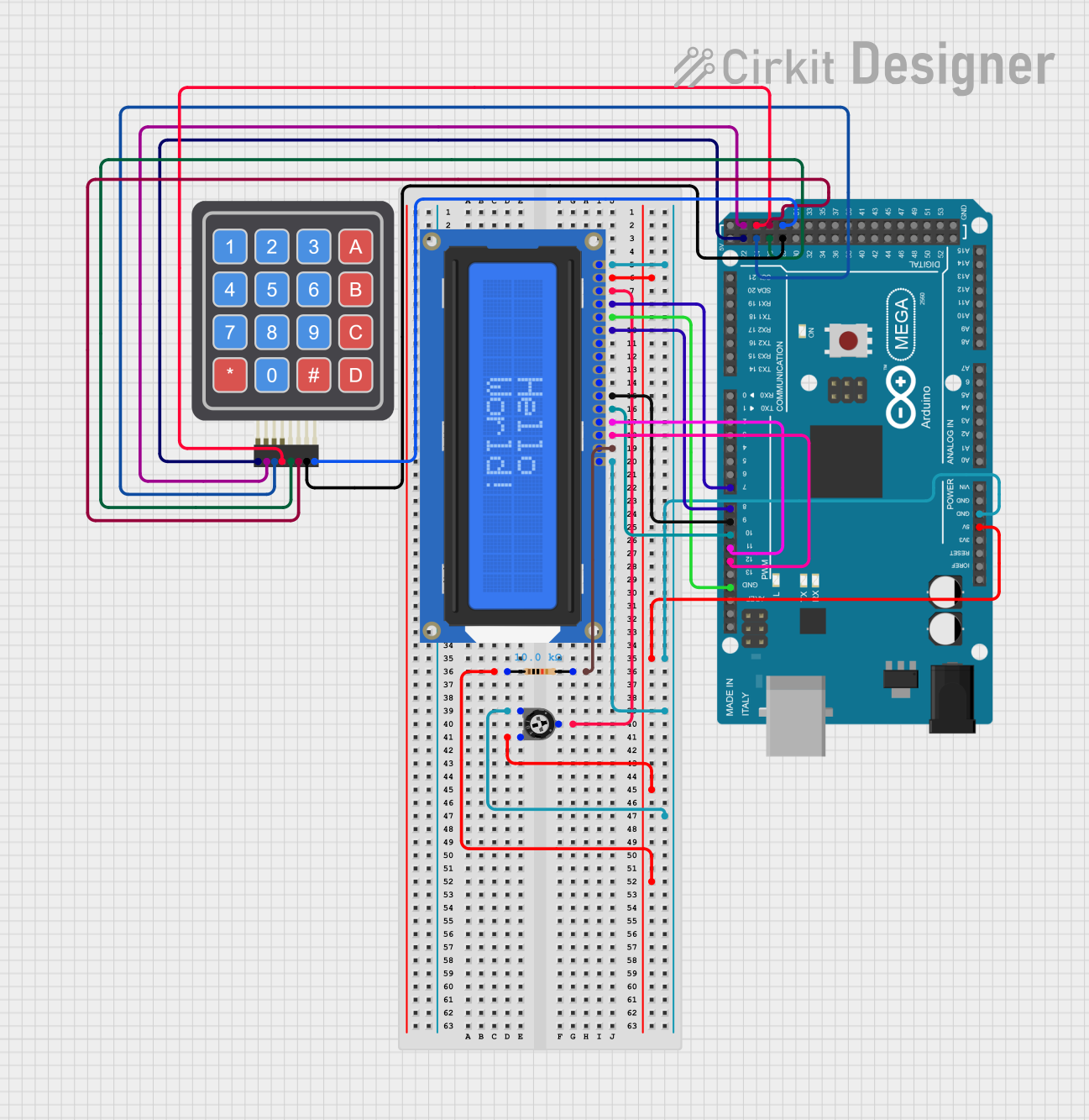
Circuit Documentation
Summary
This circuit involves an Arduino Mega 2560 microcontroller interfaced with a 4x4 Keypad, an Adafruit Standard LCD 16x2 display, a trimmer potentiometer, and a resistor. The Arduino Mega 2560 serves as the central controller, reading inputs from the keypad and displaying information on the LCD. The trimmer potentiometer is used to adjust the contrast of the LCD.
Component List
Arduino Mega 2560
- Description: A microcontroller board based on the ATmega2560.
- Pins: IOREF, RESET, 3V3, 5V, GND, VIN, A0-A15, D0-D53, AREF, SDA, SCL
4x4 Keypad (Simulator)
- Description: A 4x4 matrix keypad used for user input.
- Pins: R1, C4, R2, C2, R3, R4, C1, C3
Adafruit Standard LCD 16x2 white on blue
- Description: A 16x2 character LCD display with white text on a blue background.
- Pins: VSS, VDD, V0, RS, R/W, E, DB0-DB7, LED+, LED-
Trimmer Potentiometer
- Description: A variable resistor used to adjust the contrast of the LCD.
- Pins: leg1, wiper, leg2
- Properties: Resistance: 10k Ohms
Resistor
- Description: A fixed resistor.
- Pins: pin1, pin2
- Properties: Resistance: 10k Ohms
Wiring Details
Arduino Mega 2560
GND is connected to:
- VSS of Adafruit Standard LCD 16x2
- LED- of Adafruit Standard LCD 16x2
- R/W of Adafruit Standard LCD 16x2
- leg1 of Trimmer Potentiometer
5V is connected to:
- VDD of Adafruit Standard LCD 16x2
- pin1 of Resistor
- leg2 of Trimmer Potentiometer
D7 PWM is connected to:
- RS of Adafruit Standard LCD 16x2
D8 PWM is connected to:
- E of Adafruit Standard LCD 16x2
D9 PWM is connected to:
- DB4 of Adafruit Standard LCD 16x2
D10 PWM is connected to:
- DB5 of Adafruit Standard LCD 16x2
D11 PWM is connected to:
- DB6 of Adafruit Standard LCD 16x2
D12 PWM is connected to:
- DB7 of Adafruit Standard LCD 16x2
D22 is connected to:
- R1 of 4x4 Keypad
D23 is connected to:
- R2 of 4x4 Keypad
D24 is connected to:
- R3 of 4x4 Keypad
D25 is connected to:
- R4 of 4x4 Keypad
D26 is connected to:
- C1 of 4x4 Keypad
D27 is connected to:
- C2 of 4x4 Keypad
D28 is connected to:
- C3 of 4x4 Keypad
D29 is connected to:
- C4 of 4x4 Keypad
Adafruit Standard LCD 16x2 white on blue
VSS is connected to:
- GND of Arduino Mega 2560
- LED- of Adafruit Standard LCD 16x2
- leg1 of Trimmer Potentiometer
VDD is connected to:
- 5V of Arduino Mega 2560
- pin1 of Resistor
- leg2 of Trimmer Potentiometer
V0 is connected to:
- wiper of Trimmer Potentiometer
RS is connected to:
- D7 PWM of Arduino Mega 2560
R/W is connected to:
- GND of Arduino Mega 2560
E is connected to:
- D8 PWM of Arduino Mega 2560
DB4 is connected to:
- D9 PWM of Arduino Mega 2560
DB5 is connected to:
- D10 PWM of Arduino Mega 2560
DB6 is connected to:
- D11 PWM of Arduino Mega 2560
DB7 is connected to:
- D12 PWM of Arduino Mega 2560
LED+ is connected to:
- pin2 of Resistor
Trimmer Potentiometer
leg1 is connected to:
- GND of Arduino Mega 2560
- VSS of Adafruit Standard LCD 16x2
- LED- of Adafruit Standard LCD 16x2
leg2 is connected to:
- 5V of Arduino Mega 2560
- VDD of Adafruit Standard LCD 16x2
- pin1 of Resistor
wiper is connected to:
- V0 of Adafruit Standard LCD 16x2
Resistor
pin1 is connected to:
- 5V of Arduino Mega 2560
- VDD of Adafruit Standard LCD 16x2
- leg2 of Trimmer Potentiometer
pin2 is connected to:
- LED+ of Adafruit Standard LCD 16x2
4x4 Keypad (Simulator)
R1 is connected to:
- D22 of Arduino Mega 2560
R2 is connected to:
- D23 of Arduino Mega 2560
R3 is connected to:
- D24 of Arduino Mega 2560
R4 is connected to:
- D25 of Arduino Mega 2560
C1 is connected to:
- D26 of Arduino Mega 2560
C2 is connected to:
- D27 of Arduino Mega 2560
C3 is connected to:
- D28 of Arduino Mega 2560
C4 is connected to:
- D29 of Arduino Mega 2560
Code Documentation
Arduino Mega 2560 Code
sketch.ino
void setup() {
  // put your setup code here, to run once:

}

void loop() {
  // put your main code here, to run repeatedly:

}
documentation.txt
This document provides a comprehensive overview of the circuit, including a summary, detailed component list, wiring details, and documented code.