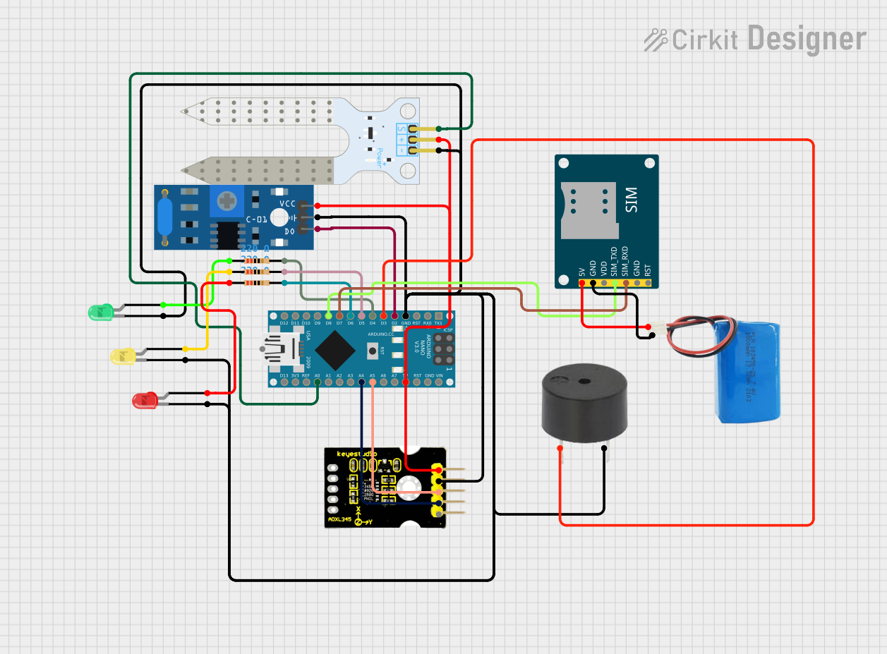
Arduino Nano-Based Landslide Detection System with GSM Alert

Circuit Documentation
Summary
This circuit is designed around an Arduino Nano microcontroller and includes a variety of sensors and modules to detect environmental conditions that may indicate a potential landslide. The circuit features a soil moisture sensor, a vibration sensor (SW-420), an accelerometer (ADXL345), a GSM module (SIM800L) for sending SMS alerts, a buzzer for audible alerts, and three LEDs (red, yellow, green) to visually indicate the status of the system. The circuit is powered by a 5V battery.
Component List
- Arduino Nano: A compact microcontroller board based on the ATmega328P, featuring digital and analog I/O pins.
- SW-420 Vibration Sensor: A module that outputs a digital signal when vibration is detected.
- Buzzer: An electronic buzzer for audible alerts.
- LED (Red, Yellow, Green): Light Emitting Diodes used for visual status indication.
- SIM800L GSM Module: A module that allows the microcontroller to communicate over GSM cellular networks to send SMS messages.
- Soil Moisture Sensor: A sensor that measures the moisture content in the soil.
- ADXL345 Accelerometer (Keystudio): A digital accelerometer that measures acceleration forces.
- Resistor (220 Ohms): Three resistors used to limit current to the LEDs.
- 5V Battery: A power source for the circuit.
Wiring Details
Arduino Nano
- GND: Connected to the ground pins of the buzzer, all LEDs, soil moisture sensor, vibration sensor, accelerometer, and GSM module.
- D2: Connected to the digital output of the SW-420 Vibration Sensor.
- D3: Connected to the buzzer.
- D4, D5, D6: Connected to the 220 Ohm resistors leading to the anodes of the green, yellow, and red LEDs, respectively.
- D7: Connected to the SIM_RXD pin of the SIM800L GSM Module.
- D8: Connected to the SIM_TXD pin of the SIM800L GSM Module.
- 5V: Powers the soil moisture sensor, vibration sensor, and accelerometer.
- A5: Connected to the SCL pin of the ADXL345 Accelerometer.
- A4: Connected to the SDA pin of the ADXL345 Accelerometer.
- A0: Connected to the signal pin of the Soil Moisture Sensor.
SW-420 Vibration Sensor
- VCC: Connected to the 5V output from the Arduino Nano.
- Ground: Connected to the GND of the Arduino Nano.
- Digital output: Connected to pin D2 of the Arduino Nano.
Buzzer
- PIN: Connected to pin D3 of the Arduino Nano.
- GND: Connected to the GND of the Arduino Nano.
LEDs (Red, Yellow, Green)
- Cathode (Red, Yellow, Green): Connected to the GND of the Arduino Nano.
- Anode (Red): Connected to a 220 Ohm resistor, then to pin D6 of the Arduino Nano.
- Anode (Yellow): Connected to a 220 Ohm resistor, then to pin D5 of the Arduino Nano.
- Anode (Green): Connected to a 220 Ohm resistor, then to pin D4 of the Arduino Nano.
SIM800L GSM Module
- 5V: Connected to the positive terminal of the 5V battery.
- GND: Connected to the negative terminal of the 5V battery.
- SIM_TXD: Connected to pin D8 of the Arduino Nano.
- SIM_RXD: Connected to pin D7 of the Arduino Nano.
Soil Moisture Sensor
- VCC: Connected to the 5V output from the Arduino Nano.
- GND: Connected to the GND of the Arduino Nano.
- SIG: Connected to pin A0 of the Arduino Nano.
ADXL345 Accelerometer (Keystudio)
- 5V: Connected to the 5V output from the Arduino Nano.
- GND: Connected to the GND of the Arduino Nano.
- SDA: Connected to pin A4 of the Arduino Nano.
- SCL: Connected to pin A5 of the Arduino Nano.
Resistor (220 Ohms)
- Pin1: Connected to the anode of the corresponding LED.
- Pin2: Connected to the respective digital pin (D4, D5, D6) of the Arduino Nano.
5V Battery
- Positive: Connected to the 5V input of the SIM800L GSM Module.
- Negative: Connected to the GND of the SIM800L GSM Module.
Documented Code
#include <Wire.h>
#include <Adafruit_Sensor.h>
#include <Adafruit_ADXL345_U.h>
#include <SoftwareSerial.h>

// Pin definitions
#define SOIL_SENSOR_PIN A0
#define VIBRATION_SENSOR_PIN 2
#define BUZZER_PIN 3
#define GREEN_LED 4
#define YELLOW_LED 5
#define RED_LED 6

// Threshold values
#define MOISTURE_THRESHOLD 500  // Soil moisture threshold
#define VIBRATION_THRESHOLD 100 // Vibration sensor threshold
#define TILT_THRESHOLD 15.0     // Tilt threshold (degrees)

// Initialize accelerometer
Adafruit_ADXL345_Unified accel = Adafruit_ADXL345_Unified(12345);

// GSM module connected to pins D7 (TX) and D8 (RX)
SoftwareSerial gsm(7, 8);

void setup() {
  // Pin Modes
  pinMode(SOIL_SENSOR_PIN, INPUT);
  pinMode(VIBRATION_SENSOR_PIN, INPUT);
  pinMode(BUZZER_PIN, OUTPUT);
  pinMode(GREEN_LED, OUTPUT);
  pinMode(YELLOW_LED, OUTPUT);
  pinMode(RED_LED, OUTPUT);

  // Initialize Serial and GSM
  Serial.begin(9600);
  gsm.begin(9600);

  // Initialize Accelerometer
  if (!accel.begin()) {
    Serial.println("No ADXL345 detected, check wiring.");
    while (1);
  }
  accel.setRange(ADXL345_RANGE_16_G); // Set range for the accelerometer
}

void loop() {
  int moistureLevel = analogRead(SOIL_SENSOR_PIN);
  int vibration = digitalRead(VIBRATION_SENSOR_PIN);

  sensors_event_t event;
  accel.getEvent(&event);
  float tilt = atan2(event.acceleration.y, event.acceleration.x) * 180 / PI;

  // Print sensor readings
  Serial.print("Soil Moisture: ");
  Serial.println(moistureLevel);
  Serial.print("Vibration: ");
  Serial.println(vibration);
  Serial.print("Tilt: ");
  Serial.println(tilt);

  // Landslide detection logic
  if (moistureLevel > MOISTURE_THRESHOLD || vibration > VIBRATION_THRESHOLD || abs(tilt) > TILT_THRESHOLD) {
    // Trigger alert
    digitalWrite(BUZZER_PIN, HIGH);
    digitalWrite(RED_LED, HIGH);
    digitalWrite(YELLOW_LED, LOW);
    digitalWrite(GREEN_LED, LOW);
    sendSMS("Warning: Possible landslide detected!");
    delay(2000);
  } else if (moistureLevel > MOISTURE_THRESHOLD || abs(tilt) > (TILT_THRESHOLD / 2)) {
    // Moderate alert
    digitalWrite(BUZZER_PIN, LOW);
    digitalWrite(RED_LED, LOW);
    digitalWrite(YELLOW_LED, HIGH);
    digitalWrite(GREEN_LED, LOW);
  } else {
    // Normal status
    digitalWrite(BUZZER_PIN, LOW);
    digitalWrite(RED_LED, LOW);
    digitalWrite(YELLOW_LED, LOW);
    digitalWrite(GREEN_LED, HIGH);
  }

  delay(1000); // Delay to avoid rapid triggering
}

// Function to send SMS alerts
void sendSMS(String message) {
  gsm.println("AT+CMGF=1");  // Set SMS mode to text
  delay(1000);
  gsm.println("AT+CMGS=\"+91xxxxxxxxxx\"");  // Replace with the recipient's phone number
  delay(1000);
  gsm.println(message);
  delay(100);
  gsm.println((char)26);  // ASCII code of CTRL+Z to send the message
  delay(1000);
}
This code is responsible for reading sensor data, determining the landslide risk level, and triggering alerts accordingly. It uses the Arduino Nano's built-in analog and digital I/O pins to interface with the sensors and modules. The sendSMS function is used to send an SMS alert when a potential landslide is detected.