
Circuit Documentation
Summary
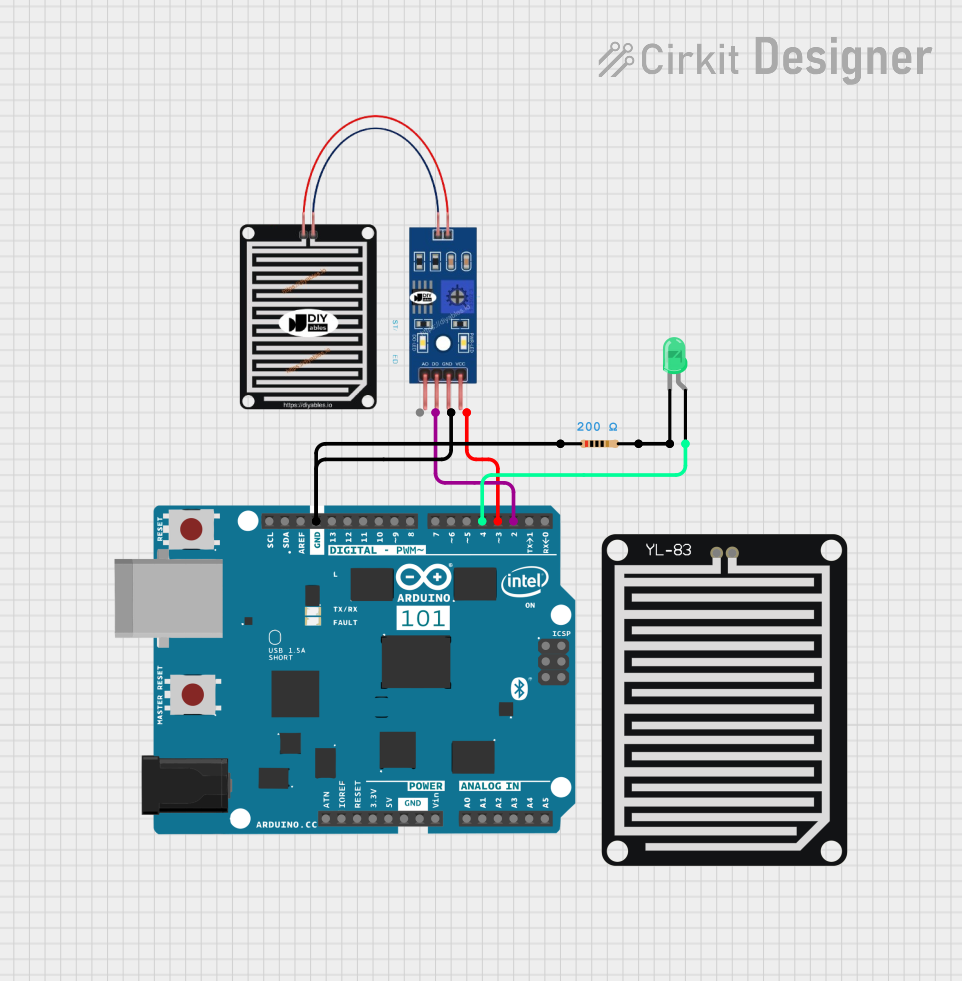
This circuit is designed to interface a rain sensor with an Arduino 101 microcontroller. The circuit also includes an LED indicator that lights up based on the sensor's output. The rain sensor detects the presence of rain and sends a digital signal to the Arduino, which then processes this signal and controls the LED accordingly.
Component List
RAIN SENSOR
- Description: A sensor used to detect the presence of rain.
- Pins: AO, DO, GRD, VCC
Arduino 101
- Description: A microcontroller board based on the Intel Curie module.
- Pins: A5/SCL, A4/SDA, AREF, GND, D13/SCK, D12/MISO, D11 PWM/MOSI, D10 PWM/SS, D9 PWM, D8, D7, D6 PWM, D5 PWM, D4, D3 PWM, D2, D1/TX, D0/RX, AIN, ioref, RESET, 3V3, 5V, VIN, A0, A1, A2, A3, ICSP MISO, ICSP SCK, ICSP MOSI
Resistor
- Description: A passive electrical component that provides resistance to the flow of current.
- Pins: pin1, pin2
- Properties:
- Resistance: 200 Ohms
LED: Two Pin (green)
- Description: A light-emitting diode that emits green light.
- Pins: cathode, anode
YL-83 Rain Sensor - Detection Board
- Description: A detection board for the YL-83 rain sensor.
- Pins: POS, NEG
Wiring Details
RAIN SENSOR
- DO is connected to D2 on the Arduino 101.
- GRD is connected to pin1 on the Resistor and GND on the Arduino 101.
- VCC is connected to D3 PWM on the Arduino 101.
Arduino 101
- D2 is connected to DO on the RAIN SENSOR.
- GND is connected to pin1 on the Resistor and GRD on the RAIN SENSOR.
- D3 PWM is connected to VCC on the RAIN SENSOR.
- D4 is connected to the anode of the LED: Two Pin (green).
Resistor
- pin1 is connected to GND on the Arduino 101 and GRD on the RAIN SENSOR.
- pin2 is connected to the cathode of the LED: Two Pin (green).
LED: Two Pin (green)
- anode is connected to D4 on the Arduino 101.
- cathode is connected to pin2 on the Resistor.
Code
No code is provided for this circuit.