
ESP32-Based Obstacle Detection and Display System with Servo Control
View and Edit Project In Cirkit Designer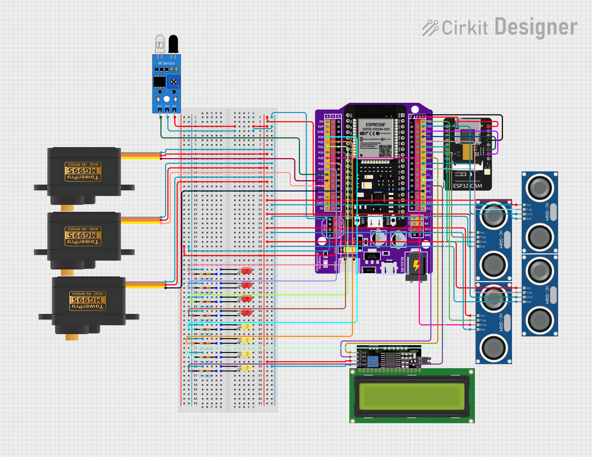
Circuit Documentation
Summary
This circuit integrates various components including microcontrollers, sensors, servomotors, an LCD display, and LEDs. The primary microcontroller is an ESP32 with a 38-pin expansion board, which interfaces with an ESP32-CAM module, multiple HC-SR04 ultrasonic sensors, IR sensors, servomotors, and LEDs. The circuit is designed to perform tasks that likely involve motion control, distance measurement, image capture, and visual feedback through LEDs and an LCD display.
Component List
Microcontrollers
- ESP32 - 38 pins Expansion Board: A microcontroller board with WiFi and Bluetooth capabilities, featuring a wide range of GPIO pins for interfacing with various peripherals.
- ESP32 - CAM: A small-sized camera module that can be connected to the ESP32 for capturing images and video.
Sensors
- IR Sensor: A sensor that detects infrared light, commonly used for proximity or object detection.
- HC-SR04 Ultrasonic Sensor: A sensor that measures distance by emitting ultrasonic waves and measuring the time taken for the echo to return.
Actuators
- Servomotor MG995: A high-torque servomotor used for precise control of mechanical movement.
Display
- LCD Display 16x4 I2C: A 16x4 character LCD display with an I2C interface for displaying text and numbers.
Indicators
- LED: Two Pin (red): A red light-emitting diode used as an indicator or for illumination.
- LED: Two Pin (yellow): A yellow light-emitting diode used as an indicator or for illumination.
Passive Components
- Resistor: A passive two-terminal electrical component that implements electrical resistance as a circuit element.
Wiring Details
ESP32 - 38 pins Expansion Board
- 5V: Connected to the VCC pins of the IR sensor, servomotors, HC-SR04 ultrasonic sensors, and LCD display.
- G: Connected to the GND pins of the IR sensor, servomotors, HC-SR04 ultrasonic sensors, LCD display, and the cathodes of all LEDs.
- 3V: Not connected.
- GPIOs (P34, P35, P32, P33, P25, P26, P27, P14, P12, P13, P23, P22, P19, P18, P5, P17, P16, P4, P0, P2, P15): Connected to various components such as HC-SR04 ultrasonic sensors (TRIG and ECHO pins), servomotors (SIG pins), IR sensor (out pin), and LCD display (SCL and SDA pins).
- TX: Connected to the VOT pin of the ESP32-CAM.
- RX: Connected to the VOR pin of the ESP32-CAM.
- V: Connected to the 3V3 pin of the ESP32-CAM.
ESP32 - CAM
- 5V: Not connected.
- GND: Connected to the G pin of the ESP32 - 38 pins Expansion Board.
- 3V3: Connected to the V pin of the ESP32 - 38 pins Expansion Board.
- VOT: Connected to the TX pin of the ESP32 - 38 pins Expansion Board.
- VOR: Connected to the RX pin of the ESP32 - 38 pins Expansion Board.
IR Sensor
- VCC: Connected to the 5V pin of the ESP32 - 38 pins Expansion Board.
- GND: Connected to the G pin of the ESP32 - 38 pins Expansion Board.
- Out: Connected to the P14 pin of the ESP32 - 38 pins Expansion Board.
Servomotor MG995
- VCC: Connected to the 5V pin of the ESP32 - 38 pins Expansion Board.
- GND: Connected to the G pin of the ESP32 - 38 pins Expansion Board.
- SIG: Connected to the P12, P13, and P15 pins of the ESP32 - 38 pins Expansion Board.
HC-SR04 Ultrasonic Sensor
- VCC: Connected to the 5V pin of the ESP32 - 38 pins Expansion Board.
- GND: Connected to the G pin of the ESP32 - 38 pins Expansion Board.
- TRIG: Connected to the P23, P22, P18, and P16 pins of the ESP32 - 38 pins Expansion Board.
- ECHO: Connected to the P25, P22, P19, and P17 pins of the ESP32 - 38 pins Expansion Board.
LCD Display 16x4 I2C
- SCL: Connected to the P5 pin of the ESP32 - 38 pins Expansion Board.
- SDA: Connected to the P4 pin of the ESP32 - 38 pins Expansion Board.
- VCC: Connected to the 5V pin of the ESP32 - 38 pins Expansion Board.
- GND: Connected to the G pin of the ESP32 - 38 pins Expansion Board.
LEDs
- Cathode (red and yellow): Connected to the G pin of the ESP32 - 38 pins Expansion Board.
- Anode (red and yellow): Connected to the pin1 of their respective resistors.
Resistors
- Pin1: Connected to the anodes of the respective LEDs.
- Pin2: Connected to various GPIOs of the ESP32 - 38 pins Expansion Board (P34, P35, P32, P33, P26, P27, P0, P2).
Documented Code
No code has been provided for the microcontrollers in this circuit. The documentation of the code would typically include descriptions of the functionality implemented by the code, such as control algorithms, communication protocols, and any specific routines for interfacing with the hardware components listed above.