
Arduino Nano Controlled Linear Actuator System with Relay and Limit Switch
View and Edit Project In Cirkit Designer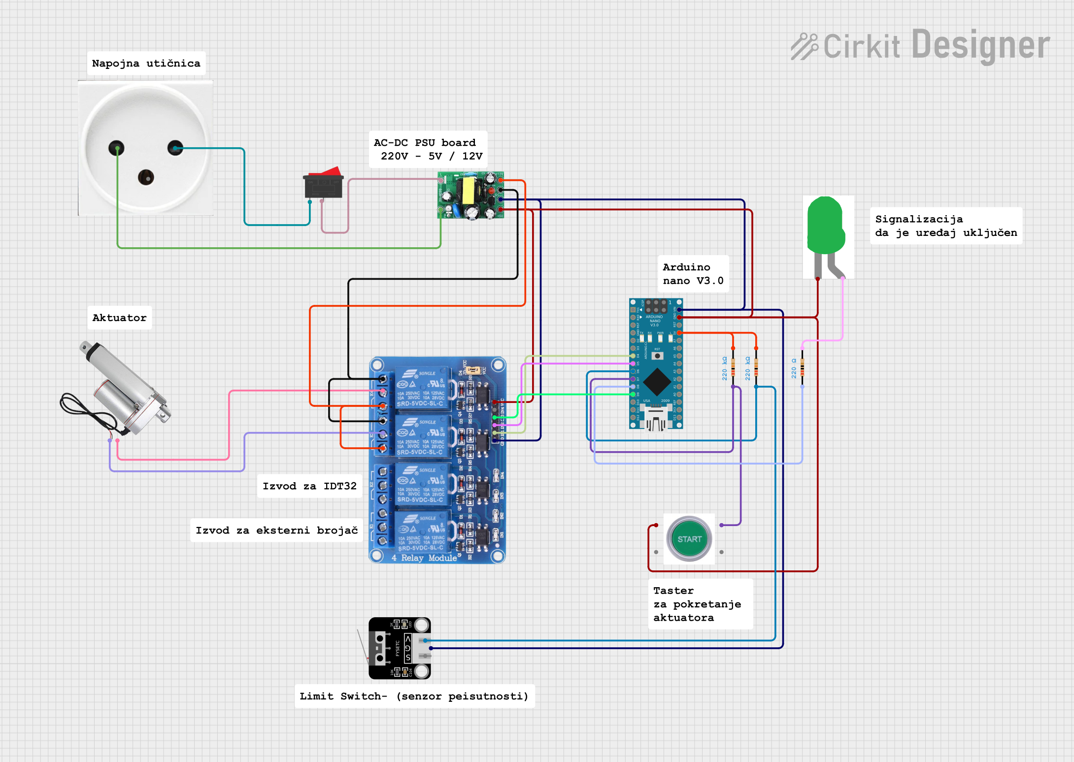
Circuit Documentation
Summary
This document provides a detailed overview of a circuit that includes a variety of components such as a linear actuator, relay, power supply unit, Arduino Nano, switches, resistors, and an LED. The circuit is designed to control the linear actuator using the Arduino Nano and relay module, with additional components for power management and user interaction.
Component List
Linear Actuator
- Pins: +, -
- Description: A device that creates motion in a straight line.
- Purpose: To provide linear motion controlled by the relay.
Relay 4 Channel 5V
- Pins: GND, IN1, IN2, IN3, IN4, VCC, COM1, COM2, COM3, COM4, NO1, NO2, NO3, NO4, NC1, NC2, NC3, NC4
- Description: A relay module with 4 channels, operating at 5V.
- Purpose: To control the linear actuator and other components.
AC-DC PSU Board 220V-5V&12V
- Pins: AC-N, AC-L, +5V, GND, +12V
- Description: A power supply unit that converts 220V AC to 5V and 12V DC.
- Purpose: To provide power to the circuit components.
Arduino Nano
- Pins: D1/TX, D0/RX, RESET, GND, D2, D3, D4, D5, D6, D7, D8, D9, D10, D11/MOSI, D12/MISO, VIN, 5V, A7, A6, A5, A4, A3, A2, A1, A0, AREF, 3V3, D13/SCK
- Description: A small, complete, and breadboard-friendly microcontroller board.
- Purpose: To control the relay and other components in the circuit.
Resistor (220k Ohms)
- Pins: pin1, pin2
- Description: A resistor with a resistance of 220k Ohms.
- Purpose: To limit current in the circuit.
Resistor (220 Ohms)
- Pins: pin1, pin2
- Description: A resistor with a resistance of 220 Ohms.
- Purpose: To limit current in the circuit.
START SWITCH
- Pins: NO 1, NC 1, NO 2, NC 2
- Description: A switch to start the circuit operation.
- Purpose: To initiate the circuit operation.
Limit Switch
- Pins: S, G, V
- Description: A switch that limits the motion of the actuator.
- Purpose: To provide feedback on the actuator's position.
Rocker Switch
- Pins: 1, 2
- Description: A switch that toggles the power supply.
- Purpose: To control the power supply to the circuit.
Power Outlet (IL)
- Pins: N, L, GND
- Description: A power outlet for connecting the PSU.
- Purpose: To provide AC power to the PSU.
LED: Two Pin (Green)
- Pins: cathode, anode
- Description: A green LED.
- Purpose: To indicate the status of the circuit.
Wiring Details
Linear Actuator
- + connected to COM3 of Relay 4 Channel 5V
- - connected to COM4 of Relay 4 Channel 5V
Relay 4 Channel 5V
- COM3 connected to + of Linear Actuator
- COM4 connected to - of Linear Actuator
- GND connected to G of Limit Switch, VIN of Arduino Nano, and GND of AC-DC PSU Board 220V-5V&12V
- IN1 connected to D4 of Arduino Nano
- IN2 connected to D5 of Arduino Nano
- IN3 connected to D9 of Arduino Nano
- VCC connected to NO 1 of START SWITCH, GND of Arduino Nano, +5V of AC-DC PSU Board 220V-5V&12V, and cathode of LED: Two Pin (Green)
- NO3 connected to NO4 of Relay 4 Channel 5V and GND of AC-DC PSU Board 220V-5V&12V
- NC3 connected to NC4 of Relay 4 Channel 5V and +12V of AC-DC PSU Board 220V-5V&12V
AC-DC PSU Board 220V-5V&12V
- AC-N connected to N of Power Outlet (IL)
- AC-L connected to 2 of Rocker Switch
- GND connected to GND of Relay 4 Channel 5V, G of Limit Switch, and VIN of Arduino Nano
- +5V connected to VCC of Relay 4 Channel 5V, NO 1 of START SWITCH, GND of Arduino Nano, and cathode of LED: Two Pin (Green)
- +12V connected to NC3 and NC4 of Relay 4 Channel 5V
Arduino Nano
- VIN connected to GND of Relay 4 Channel 5V, G of Limit Switch, and GND of AC-DC PSU Board 220V-5V&12V
- D4 connected to IN1 of Relay 4 Channel 5V
- D5 connected to IN2 of Relay 4 Channel 5V
- D6 connected to V of Limit Switch and pin1 of Resistor (220k Ohms)
- D7 connected to NO 2 of START SWITCH and pin1 of Resistor (220k Ohms)
- D8 connected to pin1 of Resistor (220 Ohms)
- D9 connected to IN3 of Relay 4 Channel 5V
- 5V connected to pin2 of Resistor (220k Ohms) and pin2 of Resistor (220 Ohms)
Resistor (220k Ohms)
- pin1 connected to V of Limit Switch and D6 of Arduino Nano
- pin2 connected to 5V of Arduino Nano
Resistor (220 Ohms)
- pin1 connected to D8 of Arduino Nano
- pin2 connected to anode of LED: Two Pin (Green)
START SWITCH
- NO 1 connected to VCC of Relay 4 Channel 5V, GND of Arduino Nano, +5V of AC-DC PSU Board 220V-5V&12V, and cathode of LED: Two Pin (Green)
- NO 2 connected to D7 of Arduino Nano and pin1 of Resistor (220k Ohms)
Limit Switch
- G connected to GND of Relay 4 Channel 5V, VIN of Arduino Nano, and GND of AC-DC PSU Board 220V-5V&12V
- V connected to D6 of Arduino Nano and pin1 of Resistor (220k Ohms)
Rocker Switch
- 1 connected to L of Power Outlet (IL)
- 2 connected to AC-L of AC-DC PSU Board 220V-5V&12V
Power Outlet (IL)
- N connected to AC-N of AC-DC PSU Board 220V-5V&12V
- L connected to 1 of Rocker Switch
LED: Two Pin (Green)
- cathode connected to VCC of Relay 4 Channel 5V, GND of Arduino Nano, +5V of AC-DC PSU Board 220V-5V&12V, and NO 1 of START SWITCH
- anode connected to pin2 of Resistor (220 Ohms)