
ESP32-Based Wi-Fi Controlled Relay System with Pushbutton and Battery Power
View and Edit Project In Cirkit Designer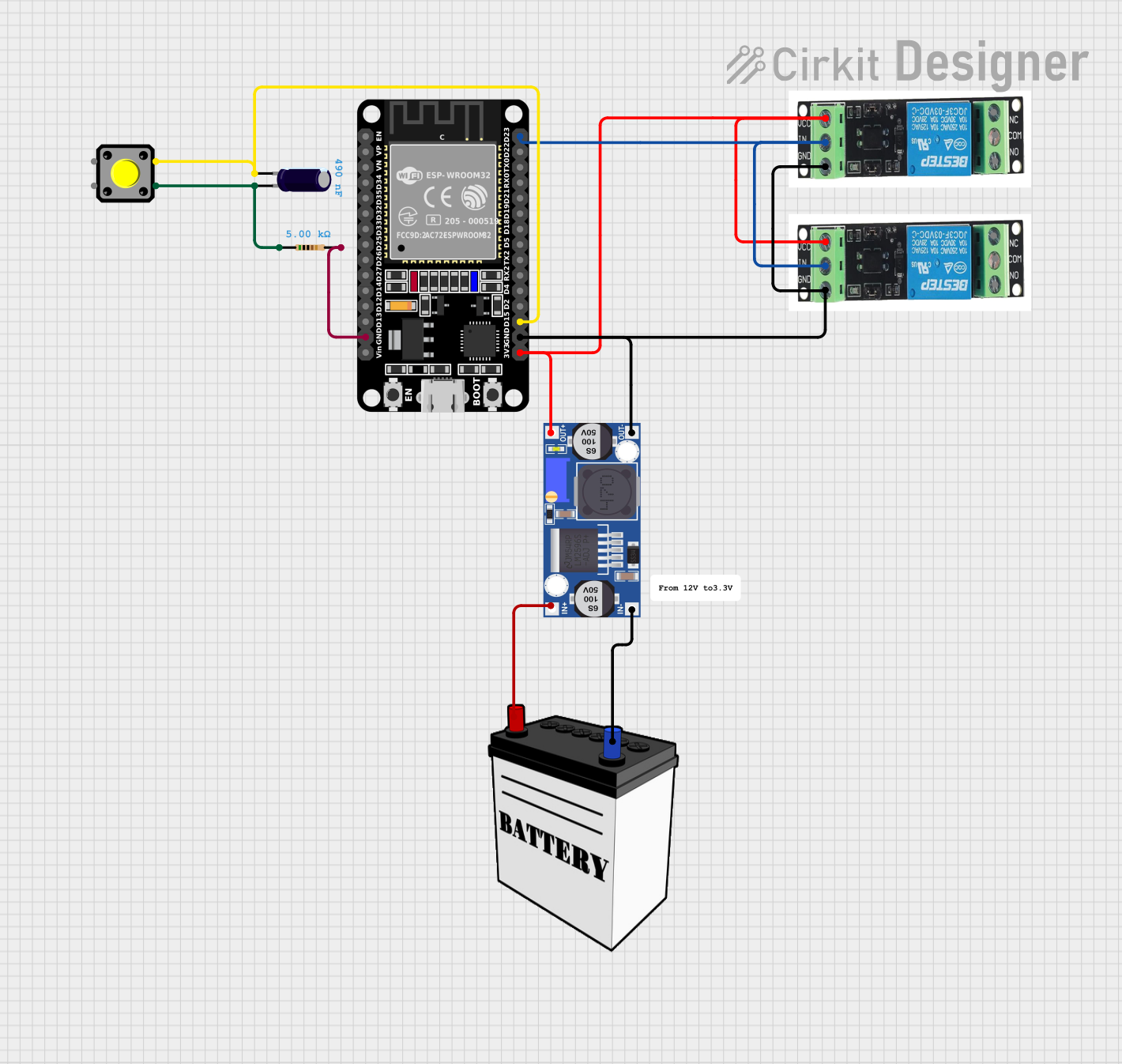
Circuit Documentation
Summary
This document provides a detailed overview of a circuit that includes an ESP32 microcontroller, a buck converter, relays, a pushbutton, a resistor, an electrolytic capacitor, and a 12V battery. The circuit is designed to control relays using the ESP32, with power regulation provided by the buck converter.
Component List
ESP32 (30 pin)
- Description: A versatile microcontroller with Wi-Fi and Bluetooth capabilities.
- Pins: EN, VP, VN, D34, D35, D32, D33, D25, D26, D27, D14, D12, D13, GND, Vin, D23, D22, TX0, RX0, D21, D19, D18, D5, TX2, RX2, D4, D2, D15, 3V3
Buck Converter
- Description: A DC-DC converter that steps down voltage from 12V to 3.3V.
- Pins: IN+, IN-, OUT+, OUT-
3.3V Relay
- Description: A relay that operates at 3.3V.
- Pins: Normally open, Common, GND, Normally closed, Signal, VI 3.3V
Pushbutton
- Description: A simple pushbutton switch.
- Pins: Pin 2, Pin 1, Pin 3, Pin 4
Electrolytic Capacitor
- Description: A capacitor with a capacitance of 4.9e-7 Farads.
- Pins: -, +
Resistor
- Description: A resistor with a resistance of 5000 Ohms.
- Pins: pin1, pin2
12V Battery
- Description: A battery providing 12V power.
- Pins: VCC, GND
Wiring Details
ESP32 (30 pin)
GND is connected to:
- Resistor pin2
- Buck converter OUT-
- Both 3.3V relay GND pins
D23 is connected to:
- Both 3.3V relay Signal pins
D15 is connected to:
- Pushbutton Pin 3
- Electrolytic Capacitor -
3V3 is connected to:
- Buck converter OUT+
- Both 3.3V relay VI 3.3V pins
Buck Converter
IN+ is connected to:
- 12V Battery VCC
IN- is connected to:
- 12V Battery GND
OUT+ is connected to:
- ESP32 3V3
- Both 3.3V relay VI 3.3V pins
OUT- is connected to:
- ESP32 GND
- Both 3.3V relay GND pins
3.3V Relay
Signal is connected to:
- ESP32 D23
GND is connected to:
- Buck converter OUT-
- ESP32 GND
VI 3.3V is connected to:
- Buck converter OUT+
- ESP32 3V3
Pushbutton
Pin 2 is connected to:
- Resistor pin1
- Electrolytic Capacitor +
Pin 3 is connected to:
- ESP32 D15
- Electrolytic Capacitor -
Electrolytic Capacitor
+ is connected to:
- Pushbutton Pin 2
- Resistor pin1
- is connected to:
- Pushbutton Pin 3
- ESP32 D15
Resistor
pin1 is connected to:
- Pushbutton Pin 2
- Electrolytic Capacitor +
pin2 is connected to:
- ESP32 GND
12V Battery
VCC is connected to:
- Buck converter IN+
GND is connected to:
- Buck converter IN-
Code
No code is provided for this circuit.
This document provides a comprehensive overview of the circuit, including a summary, component list, wiring details, and code documentation. Each component is described in detail, and the wiring connections are clearly outlined to ensure proper assembly and functionality.