
Arduino-Based Coin Counter with IR Sensors and Servo-Controlled Heat Sealer
View and Edit Project In Cirkit Designer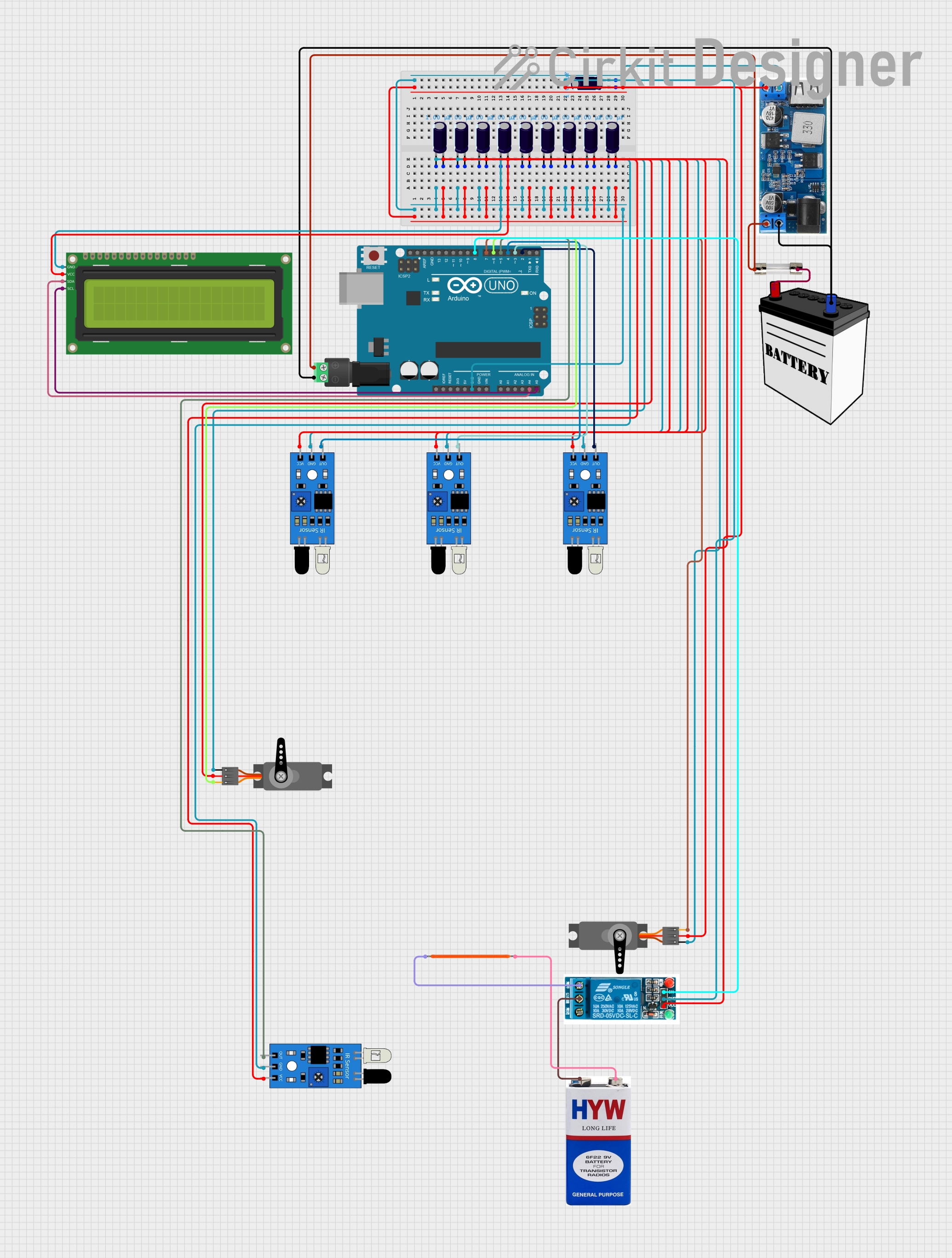
Circuit Documentation
Summary
This circuit is a coin counter and heat sealer system. It uses multiple IR sensors to detect different coin denominations, an Arduino UNO to process the inputs, and servos to control a door and a heat sealer. The system also includes an LCD display to show the coin count and a relay to control the heat sealer.
Component List
IR Sensor
- Description: Infrared sensor used to detect coins.
- Pins: out, gnd, vcc
Servo
- Description: Servo motor used to control the door and heat sealer.
- Pins: GND, VCC, PWM
5V Relay
- Description: Relay used to control the heat sealer.
- Pins: Normally Open, Common terminal, Normally Closed, In, GND, VCC
LED Filament 3V
- Description: LED used for visual indication.
- Pins: GND, Vcc
16x2 I2C LCD
- Description: LCD display used to show the coin count.
- Pins: GND, VCC, SDA, SCL
24/12V Buck Converter
- Description: Buck converter used to step down voltage.
- Pins: VIN+, VIN-, 5V, GND
12V Battery
- Description: Power source for the circuit.
- Pins: VCC, GND
Electrolytic Capacitor
- Description: Capacitor used for filtering.
- Pins: -, +
- Properties: Capacitance: 0.000001 Farads
2.1mm Barrel Jack with Terminal Block
- Description: Power input connector.
- Pins: POS, NEG
5A Fuse
- Description: Fuse for overcurrent protection.
- Pins: input, output
Arduino UNO
- Description: Microcontroller used to process inputs and control outputs.
- Pins: UNUSED, IOREF, Reset, 3.3V, 5V, GND, Vin, A0, A1, A2, A3, A4, A5, SCL, SDA, AREF, D13, D12, D11, D10, D9, D8, D7, D6, D5, D4, D3, D2, D1, D0
9V Battery
- Description: Additional power source.
- Pins: +, -
Wiring Details
IR Sensor
gnd connected to:
- Electrolytic Capacitor (-)
- 16x2 I2C LCD (GND)
- Servo (GND)
- Arduino UNO (GND)
- 5V Relay (GND)
- 24/12V Buck (GND)
vcc connected to:
- Electrolytic Capacitor (+)
- 16x2 I2C LCD (VCC)
- Servo (VCC)
- 5V Relay (VCC)
- 24/12V Buck (5V)
out connected to:
- Arduino UNO (D2, D3, D4, D5)
Servo
GND connected to:
- Electrolytic Capacitor (-)
- 16x2 I2C LCD (GND)
- Arduino UNO (GND)
- 5V Relay (GND)
- 24/12V Buck (GND)
VCC connected to:
- Electrolytic Capacitor (+)
- 16x2 I2C LCD (VCC)
- 5V Relay (VCC)
- 24/12V Buck (5V)
PWM connected to:
- Arduino UNO (D6, D7)
5V Relay
GND connected to:
- Electrolytic Capacitor (-)
- 16x2 I2C LCD (GND)
- Servo (GND)
- Arduino UNO (GND)
- 24/12V Buck (GND)
VCC connected to:
- Electrolytic Capacitor (+)
- 16x2 I2C LCD (VCC)
- Servo (VCC)
- 24/12V Buck (5V)
In connected to:
- Arduino UNO (D8)
Normally Open connected to:
- LED Filament 3V (Vcc)
Common terminal connected to:
- 9V Battery (+)
LED Filament 3V
GND connected to:
- 9V Battery (-)
Vcc connected to:
- 5V Relay (Normally Open)
16x2 I2C LCD
GND connected to:
- Electrolytic Capacitor (-)
- Servo (GND)
- Arduino UNO (GND)
- 5V Relay (GND)
- 24/12V Buck (GND)
VCC connected to:
- Electrolytic Capacitor (+)
- Servo (VCC)
- 5V Relay (VCC)
- 24/12V Buck (5V)
SDA connected to:
- Arduino UNO (A4)
SCL connected to:
- Arduino UNO (A5)
24/12V Buck Converter
VIN+ connected to:
- 2.1mm Barrel Jack with Terminal Block (POS)
- 5A Fuse (output)
VIN- connected to:
- 2.1mm Barrel Jack with Terminal Block (NEG)
- 12V Battery (GND)
5V connected to:
- Electrolytic Capacitor (+)
- 16x2 I2C LCD (VCC)
- Servo (VCC)
- 5V Relay (VCC)
GND connected to:
- Electrolytic Capacitor (-)
- 16x2 I2C LCD (GND)
- Servo (GND)
- Arduino UNO (GND)
- 5V Relay (GND)
12V Battery
VCC connected to:
- 5A Fuse (input)
GND connected to:
- 24/12V Buck (VIN-)
Electrolytic Capacitor
- connected to:
- IR Sensor (gnd)
- 16x2 I2C LCD (GND)
- Servo (GND)
- Arduino UNO (GND)
- 5V Relay (GND)
- 24/12V Buck (GND)
+ connected to:
- IR Sensor (vcc)
- 16x2 I2C LCD (VCC)
- Servo (VCC)
- 5V Relay (VCC)
- 24/12V Buck (5V)
2.1mm Barrel Jack with Terminal Block
POS connected to:
- 24/12V Buck (VIN+)
- 5A Fuse (output)
NEG connected to:
- 24/12V Buck (VIN-)
- 12V Battery (GND)
5A Fuse
input connected to:
- 12V Battery (VCC)
output connected to:
- 2.1mm Barrel Jack with Terminal Block (POS)
- 24/12V Buck (VIN+)
Arduino UNO
GND connected to:
- Electrolytic Capacitor (-)
- 16x2 I2C LCD (GND)
- Servo (GND)
- 5V Relay (GND)
- 24/12V Buck (GND)
A4 connected to:
- 16x2 I2C LCD (SDA)
A5 connected to:
- 16x2 I2C LCD (SCL)
D2 connected to:
- IR Sensor (out)
D3 connected to:
- IR Sensor (out)
D4 connected to:
- IR Sensor (out)
D5 connected to:
- IR Sensor (out)
D6 connected to:
- Servo (PWM)
D7 connected to:
- Servo (PWM)
D8 connected to:
- 5V Relay (In)
Code Documentation
#include <Servo.h>
#include <Wire.h>
#include <LiquidCrystal_I2C.h>

// Define pins for IR sensors
#define IR_1_PIN 2   // 1 Peso coin
#define IR_2_PIN 3   // 5 Peso coin
#define IR_3_PIN 4   // 10 Peso coin
#define IR_4_PIN 5   // 4th sensor for relay and heat sealer