Arduino UNO Controlled LED and Buzzer Notification System with Ultrasonic Sensor
Circuit Documentation
Summary
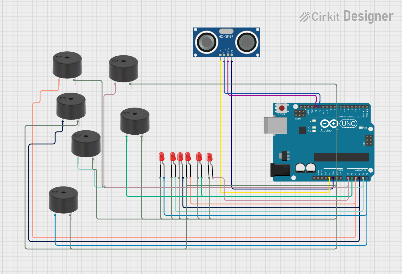
The circuit in question is designed around an Arduino UNO microcontroller, which serves as the central processing unit. The circuit includes a series of red two-pin LEDs and buzzers, as well as an HC-SR04 Ultrasonic Sensor. The LEDs and buzzers are connected to various digital I/O pins on the Arduino, allowing for control of these components through software. The ultrasonic sensor is connected to both a digital input and output pin for triggering and receiving echo signals, respectively. Power is supplied to the sensor through the Arduino's 5V output, and all components share a common ground connection.
Component List
Arduino UNO: A microcontroller board based on the ATmega328P. It has 14 digital input/output pins, 6 analog inputs, a USB connection, a power jack, an ICSP header, and a reset button.
LED: Two Pin (red): A basic red LED with an anode and cathode for indicating status or for simple display purposes.
Buzzer: An electromechanical component that can emit a tone when an electrical signal is applied.
HC-SR04 Ultrasonic Sensor: A sensor that can measure distance by emitting ultrasonic waves and measuring the time it takes for the echo to return.
Wiring Details
Arduino UNO
- 5V: Supplies power to the HC-SR04 Ultrasonic Sensor.
- GND: Common ground for the HC-SR04 Ultrasonic Sensor, all LEDs, and buzzers.
- A0 - A5: Connected to the anodes of LEDs and pins of buzzers for control.
- D12 (TRIG): Connected to the TRIG pin of the HC-SR04 Ultrasonic Sensor to initiate distance measurement.
- D13 (ECHO): Connected to the ECHO pin of the HC-SR04 Ultrasonic Sensor to receive the reflected signal.
LED: Two Pin (red)
- Anode: Connected to Arduino UNO pins A0 - A5 for control.
- Cathode: Connected to the common ground.
Buzzer
- PIN: Connected to Arduino UNO pins A0 - A5 for control.
- GND: Connected to the common ground.
HC-SR04 Ultrasonic Sensor
- VCC: Connected to the 5V output of the Arduino UNO.
- TRIG: Connected to pin D12 of the Arduino UNO.
- ECHO: Connected to pin D13 of the Arduino UNO.
- GND: Connected to the common ground.
Documented Code
void setup() {
  // put your setup code here, to run once:

}

void loop() {
  // put your main code here, to run repeatedly:

}
The provided code is a template with empty setup() and loop() functions, which are the standard structure for Arduino sketches. The setup() function is intended for code that needs to run once at startup, such as pin mode declarations. The loop() function contains code that will run continuously, allowing the microcontroller to perform tasks repeatedly. The actual implementation details need to be filled in based on the desired behavior of the circuit.