ESP8266 NodeMCU Controlled LED Indicator
Circuit Documentation
Summary of the Circuit
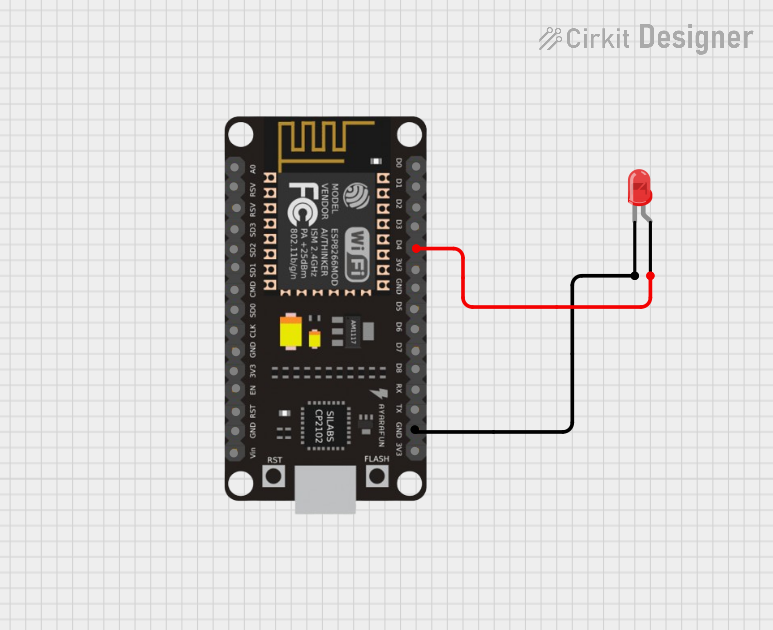
The circuit in question is a simple LED control circuit utilizing an ESP8266 NodeMCU microcontroller. The purpose of this circuit is to provide power to an LED, which can be controlled via one of the digital pins (D4) of the ESP8266 NodeMCU. The LED used in this circuit is a two-pin red LED. The circuit is powered by the 3.3V supply from the ESP8266 NodeMCU, and the LED is connected to the ground (GND) through its cathode to complete the circuit.
Component List
ESP8266 NodeMCU
- Description: A Wi-Fi capable microcontroller module based on the ESP8266 chip.
- Pins: D0, D1, D2, D3, D4, 3V3, GND, D5, D6, D7, D8, RX, TX, A0, RSV, SD3, SD2, SD1, CMD, SD0, CLK, EN, RST, VIN
- Purpose: Acts as the main controller for the circuit, providing GPIO pins for interfacing with external components like LEDs.
LED: Two Pin (red)
- Description: A basic red LED with an anode and cathode for simple light-emitting applications.
- Pins: cathode, anode
- Purpose: Serves as the output device in the circuit, emitting light when powered.
Wiring Details
ESP8266 NodeMCU
- D4: Connected to the anode of the LED.
- GND: Connected to the cathode of the LED.
LED: Two Pin (red)
- Anode: Connected to the D4 pin of the ESP8266 NodeMCU.
- Cathode: Connected to the GND pin of the ESP8266 NodeMCU.
Documented Code
Since no code was provided for the microcontroller, this section is not applicable for the current documentation. However, in a typical application, the code would be used to control the state of the LED (on/off) by setting the D4 pin to a high or low voltage level.
Please note that the actual implementation of the code would be necessary to control the LED's behavior, such as blinking or responding to external inputs. Without the code, the LED will remain in its default state, which is off unless the D4 pin is manually set to high by other means.