
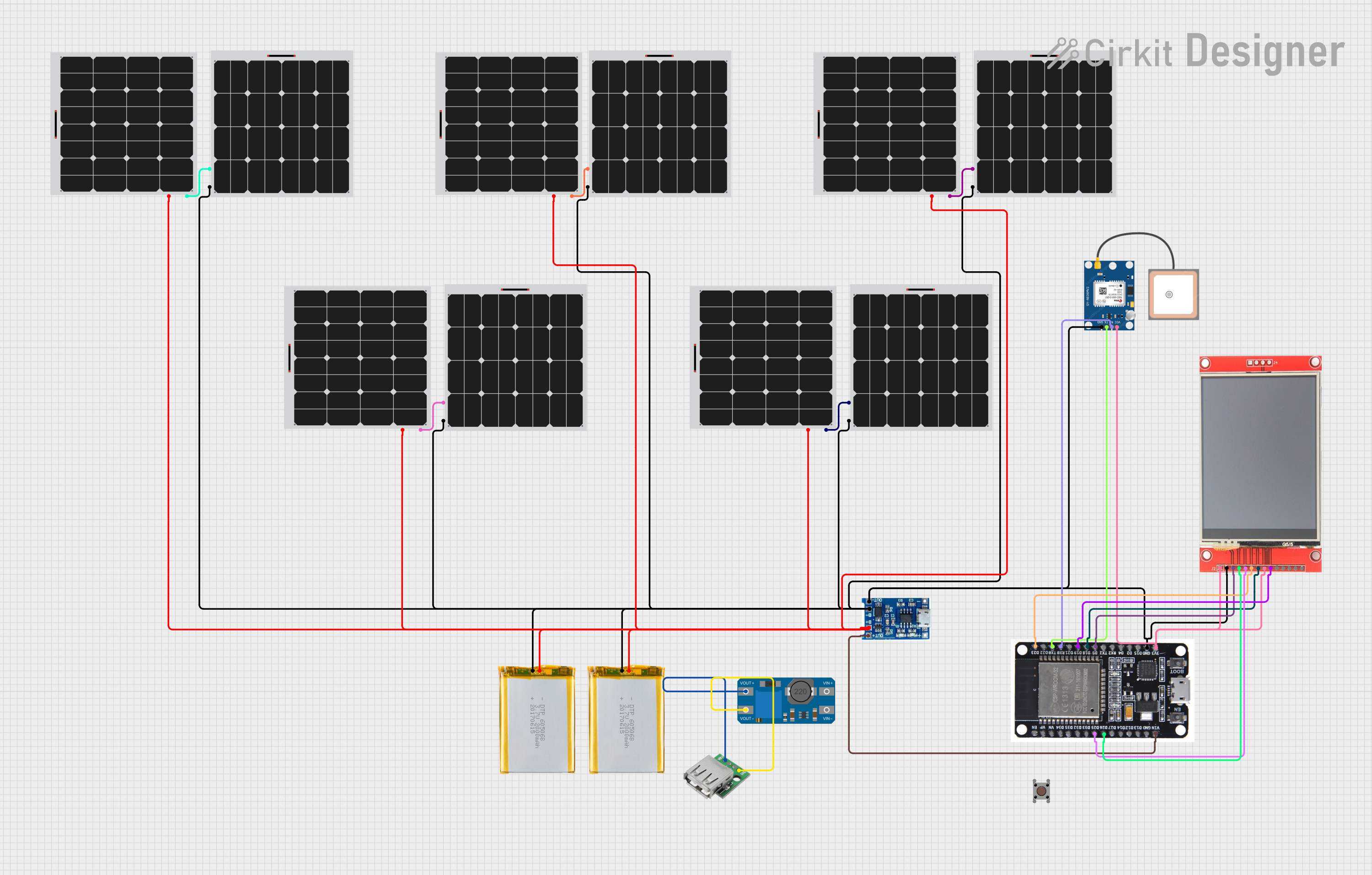
Circuit Documentation
Summary
This circuit is designed to interface an ESP32 microcontroller with a GPS NEO 6M module and an ILI9341 TFT display. The system is powered by a combination of solar panels and a 2000mAh battery, which is managed by a LiPo battery charger module. The ESP32 reads GPS coordinates from the GPS module and displays them on the TFT display. The circuit also includes a USB female connector for additional power input and an MT3608 module for voltage regulation.
Component List
2000mAh Battery
- Description: Rechargeable battery providing power to the circuit.
- Pins: VCC, GND
LiPo Battery Charger Module
- Description: Manages the charging of the 2000mAh battery using solar panels.
- Pins: B-, B+, OUT-, OUT+
GPS NEO 6M
- Description: GPS module for obtaining current coordinates.
- Pins: VCC, RX, TX, GND
ESP32
- Description: Microcontroller for processing GPS data and controlling the TFT display.
- Pins: EN, VP, VN, D34, D35, D32, D33, D25, D26, D27, D14, D12, D13, GND, VIN, 3V3, D15, D2, D4, RX2, TX2, D5, D18, D19, D21, RX0, TX0, D22, D23, BOOT
ILI9341 TFT Display
- Description: Display for showing GPS coordinates.
- Pins: VCC, GND, CS, RESET, DC/RS, SDI, SCK, LED, SDO, T_CLK, T_CS, T_DIN, T_DO, T_IRQ
Solar Panel
- Description: Provides power to the circuit by converting solar energy.
- Pins: +, -
USB Female
- Description: Provides an additional power input option.
- Pins: VCC, GND, -D, +D
MT3608
- Description: Voltage regulator module.
- Pins: VOUT+, VIN+, VOUT-, VIN-
Pushbutton
- Description: User input for triggering actions.
- Pins: Pin 3 (out), Pin 4 (out), Pin 1 (in), Pin 2 (in)
Wiring Details
2000mAh Battery
- VCC: Connected to the B+ pin of the LiPo battery charger module and the positive terminals of multiple solar panels.
- GND: Connected to the B- pin of the LiPo battery charger module and the negative terminals of multiple solar panels.
LiPo Battery Charger Module
- B+: Connected to the VCC pin of the 2000mAh battery and the positive terminals of multiple solar panels.
- B-: Connected to the GND pin of the 2000mAh battery and the negative terminals of multiple solar panels.
- OUT+: Connected to the VIN pin of the ESP32.
- OUT-: Connected to the GND pins of the ESP32, GPS NEO 6M, and ILI9341 TFT display.
GPS NEO 6M
- VCC: Connected to the 3V3 pin of the ESP32.
- RX: Connected to the RX0 pin of the ESP32.
- TX: Connected to the TX0 pin of the ESP32.
- GND: Connected to the OUT- pin of the LiPo battery charger module.
ESP32
- VIN: Connected to the OUT+ pin of the LiPo battery charger module.
- 3V3: Connected to the VCC pin of the ILI9341 TFT display and the VCC pin of the GPS NEO 6M.
- GND: Connected to the OUT- pin of the LiPo battery charger module.
- RX0: Connected to the RX pin of the GPS NEO 6M.
- TX0: Connected to the TX pin of the GPS NEO 6M.
- D25: Connected to the DC/RS pin of the ILI9341 TFT display.
- D26: Connected to the RESET pin of the ILI9341 TFT display.
- D5: Connected to the CS pin of the ILI9341 TFT display.
- D18: Connected to the SCK pin of the ILI9341 TFT display.
- D19: Connected to the SDO pin of the ILI9341 TFT display.
- D23: Connected to the SDI pin of the ILI9341 TFT display.
ILI9341 TFT Display
- VCC: Connected to the 3V3 pin of the ESP32.
- GND: Connected to the OUT- pin of the LiPo battery charger module.
- CS: Connected to the D5 pin of the ESP32.
- RESET: Connected to the D26 pin of the ESP32.
- DC/RS: Connected to the D25 pin of the ESP32.
- SDI: Connected to the D23 pin of the ESP32.
- SCK: Connected to the D18 pin of the ESP32.
- SDO: Connected to the D19 pin of the ESP32.
- LED: Connected to the 3V3 pin of the ESP32.
Solar Panel
- +: Connected to the B+ pin of the LiPo battery charger module and the VCC pin of the 2000mAh battery.
- -: Connected to the B- pin of the LiPo battery charger module and the GND pin of the 2000mAh battery.
USB Female
- VCC: Connected to the VOUT+ pin of the MT3608.
- GND: Connected to the VOUT- pin of the MT3608.
MT3608
- VOUT+: Connected to the VCC pin of the USB female connector.
- VOUT-: Connected to the GND pin of the USB female connector.
Pushbutton
- Pin 3 (out): Not connected in this circuit.
- Pin 4 (out): Not connected in this circuit.
- Pin 1 (in): Not connected in this circuit.
- Pin 2 (in): Not connected in this circuit.
Code Documentation
/*
 * This Arduino Sketch is designed for an ESP32 microcontroller. It interfaces
 * with a GPS NEO 6M module to get the current coordinates and displays them
 * on an ILI9341 TFT display. The coordinates are updated every 5 seconds.
 */

#include <Wire.h>
#include <Adafruit_GFX.h>
#include <Adafruit_ILI9341.h>
#include <TinyGPS++.h>

// GPS module connections
#define GPS_RX_PIN 3  // RX0
#define GPS_TX_PIN 1  // TX0

// TFT display connections
#define TFT_CS 5
#define TFT_RST 26
#define TFT_DC 25
#define TFT_SCK 18
#define TFT_SDO 19
#define TFT_SDI 23

// Create instances for GPS and TFT display
TinyGPSPlus gps;
Adafruit_ILI9341 tft = Adafruit_ILI9341(TFT_CS, TFT_DC, TFT_RST);

void setup() {
  // Initialize serial communication for GPS
  Serial.begin(9600);
  Serial2.begin(9600, SERIAL_8N1, GPS_RX_PIN, GPS_TX_PIN);

  // Initialize the TFT display
  tft.begin();
  tft.setRotation(3);
  tft.fillScreen(ILI9341_BLACK);
  tft.setTextColor(ILI9341_WHITE);
  tft.setTextSize(2);

  // Display initial message
  tft.setCursor(10, 10);
  tft.println("Waiting for GPS signal...");
}

void loop() {
  // Read data from GPS module
  while (Serial2.available() > 0) {
    gps.encode(Serial2.read());
  }

  // Check if GPS data is valid
  if (gps.location.isUpdated()) {
    // Clear the screen
    tft.fillScreen(ILI9341_BLACK);

    // Display latitude
    tft.setCursor(10, 10);
    tft.print("Latitude: ");
    tft.println(gps.location.lat(), 6);

    // Display longitude
    tft.setCursor(10, 40);
    tft.print("Longitude: ");
    tft.println(gps.location.lng(), 6);
  }

  // Wait for 5 seconds before updating again
  delay(5000);
}
This code initializes the ESP32 to read data from the GPS NEO 6M module and display the coordinates on the ILI9341 TFT display. The coordinates are updated every 5 seconds.