Cirkit Designer
Your all-in-one circuit design IDE
Home /
Project Documentation
Arduino UNO Based Gas Leak Detector with GSM Notification and Servo Valve Control
Circuit Documentation
Summary
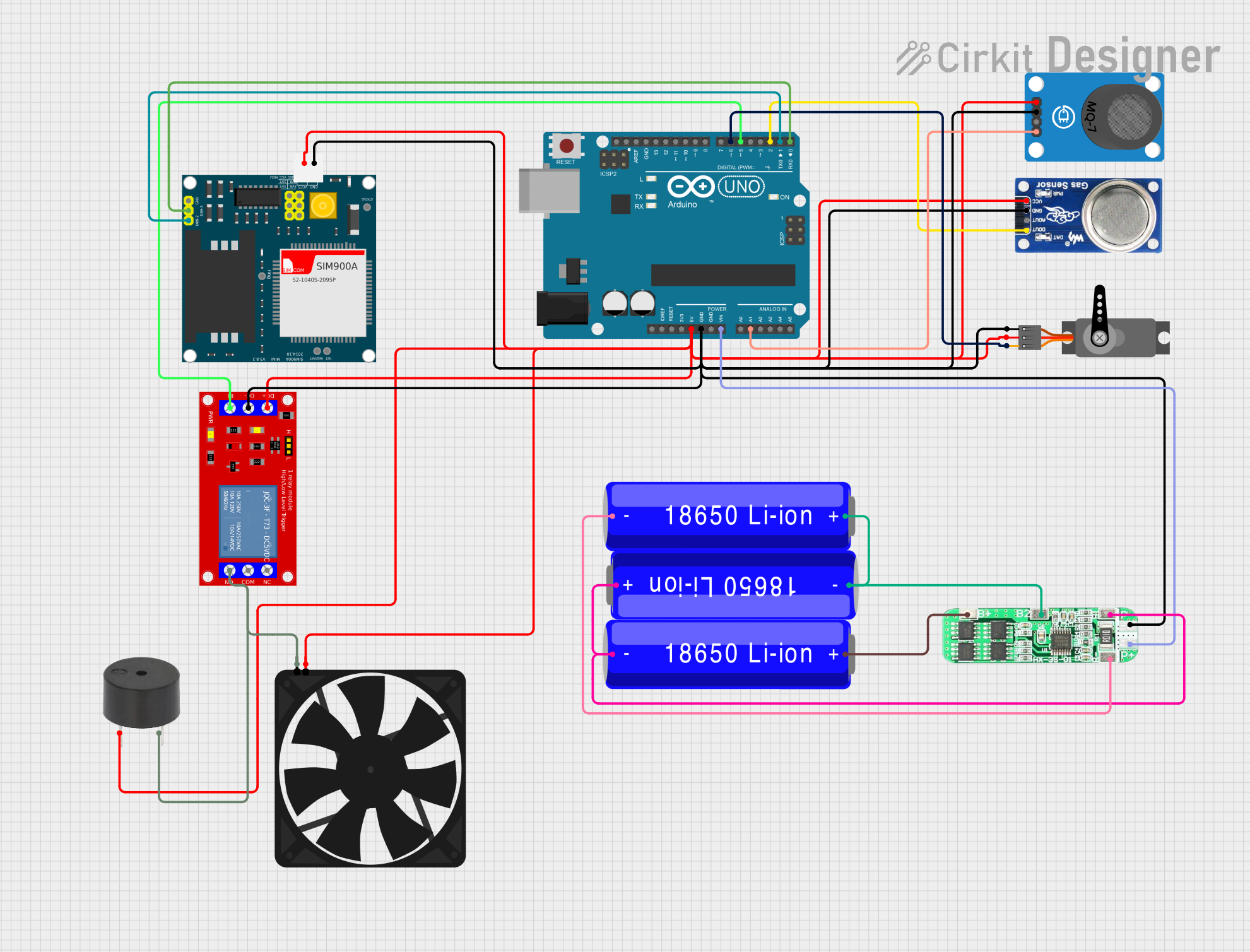
This circuit is designed to monitor and respond to gas levels using MQ-7 and MQ-6 gas sensors for carbon monoxide (CO) and liquefied petroleum gas (LPG) detection, respectively. It utilizes an Arduino UNO as the central microcontroller to process sensor readings and control peripheral devices such as a servo motor, a buzzer, a fan, and a GSM module for communication. The circuit is powered by a series of 18650 Li-ion batteries managed by a 3S 10A Li-ion Charger Protection Board Module. A relay module is used to control the fan, and the servo motor is used to operate a valve mechanism in response to gas detection.
Component List
- Arduino UNO: A microcontroller board based on the ATmega328P, featuring digital and analog I/O pins.
- Servo: An actuator that can be precisely controlled to rotate to different angles.
- MQ-7 Breakout: A carbon monoxide (CO) sensor module.
- SIM900A: A GSM/GPRS module for cellular communication.
- Buzzer: An electronic device that emits sound.
- Fan: An electric device used to create airflow.
- 3S 10A Li-ion 18650 Charger Protection Board Module: A protection module for charging and managing 18650 Li-ion batteries.
- 18650 Li-ion Battery: A rechargeable battery used to power the circuit.
- 1 Channel 5V Relay Module: A module that allows control of high power devices with low power signals.
- MQ6: A liquefied petroleum gas (LPG) sensor module.
Wiring Details
Arduino UNO
- 5V: Powers the MQ-7 Breakout, Fan, MQ6, SIM900A, 1 Channel 5V Relay Module, buzzer, and Servo.
- GND: Common ground for MQ-7 Breakout, 3S 10A Li-ion Charger Protection Board Module, MQ6, SIM900A, 1 Channel 5V Relay Module, Servo, Fan, and buzzer.
- Vin: Connected to the P+ of the 3S 10A Li-ion Charger Protection Board Module.
- A1: Receives analog output from MQ-7 Breakout.
- D6: PWM output to control the Servo.
- D5: Digital output to control the 1 Channel 5V Relay Module.
- D2: Digital input from MQ6.
- D1 (TX): Transmits data to SIM900A.
- D0 (RX): Receives data from SIM900A.
Servo
- GND: Connected to common ground.
- VCC: Powered by the 5V from Arduino UNO.
- PWM: Controlled by D6 on Arduino UNO.
MQ-7 Breakout
- VCC: Powered by the 5V from Arduino UNO.
- GND: Connected to common ground.
- AO: Analog output to A1 on Arduino UNO.
SIM900A
- GND: Connected to common ground.
- 5V: Powered by the 5V from Arduino UNO.
- DB9-3 (RXD): Receives data from D0 (RX) on Arduino UNO.
- DB9-2 (TXD): Transmits data to D1 (TX) on Arduino UNO.
Buzzer
- PIN: Powered by the 5V from Arduino UNO.
- GND: Connected to common ground.
Fan
- 5V: Powered by the 5V from Arduino UNO.
- GND: Connected to common ground.
3S 10A Li-ion 18650 Charger Protection Board Module
- P-: Connected to common ground.
- P+: Connected to Vin on Arduino UNO.
- B+: Connected to the positive terminal of the first 18650 Li-ion Battery.
- B2: Interconnection between the positive terminal of the second 18650 Li-ion Battery and the negative terminal of the third 18650 Li-ion Battery.
- B1: Interconnection between the positive terminal of the third 18650 Li-ion Battery and the negative terminal of the first 18650 Li-ion Battery.
- B-: Connected to the negative terminal of the second 18650 Li-ion Battery.
1 Channel 5V Relay Module
- VCC+: Powered by the 5V from Arduino UNO.
- VCC- (GND): Connected to common ground.
- IN: Controlled by D5 on Arduino UNO.
MQ6
- VCC: Powered by the 5V from Arduino UNO.
- GND: Connected to common ground.
- DO: Digital output to D2 on Arduino UNO.
Documented Code
#include <Servo.h>        // Include the Servo library for controlling the servo motor
#include <SoftwareSerial.h> // Include the SoftwareSerial library for GSM communication

// Pin definitions
#define MQ2_PIN A0          // Analog pin connected to MQ-2 LPG gas sensor
#define MQ7_PIN A1          // Analog pin connected to MQ-7 CO gas sensor
#define BUZZER_PIN 8        // Digital pin connected to the buzzer
#define FAN_PIN 7           // Digital pin connected to the exhaust fan via a relay
#define GSM_RX 10           // GSM Module RX pin connected to Arduino TX
#define GSM_TX 11           // GSM Module TX pin connected to Arduino RX
#define WATCHDOG_PIN 6      // Digital pin connected to the watchdog timer reset
#define SERVO_PIN 9         // Digital PWM pin connected to the servo motor

Servo myServo;              // Create a Servo object
SoftwareSerial gsm(GSM_RX, GSM_TX); // Create a SoftwareSerial object for GSM

// Thresholds for gas detection
int lpgThreshold = 300;     // Threshold value for LPG detection (adjust as necessary)
int coThreshold = 300;      // Threshold value for CO detection (adjust as necessary)

void setup() {
  pinMode(BUZZER_PIN, OUTPUT);    // Set buzzer pin as output
  pinMode(FAN_PIN, OUTPUT);       // Set fan pin as output
  pinMode(WATCHDOG_PIN, OUTPUT);  // Set watchdog pin as output
  myServo.attach(SERVO_PIN);      // Attach the servo motor to the defined pin

  Serial.begin(9600);             // Initialize serial communication for debugging
  gsm.begin(9600);                // Initialize GSM communication

  myServo.write(0);               // Set initial position of the servo motor (open valve)
  digitalWrite(WATCHDOG_PIN, HIGH); // Keep the watchdog timer reset initially

  // Send initial ready message via GSM
  gsm.println("AT+CMGF=1"); // Set SMS mode
  delay(1000);
  gsm.println("AT+CMGS=\"+91xxxxxxxxxx\""); // Replace with your mobile number
  delay(1000);
  gsm.print("LPG Gas Leakage Detection System is now active.");
  delay(100);
  gsm.write(26);  // ASCII code for CTRL+Z to send SMS
  delay(1000);
}

void loop() {
  int lpgLevel = analogRead(MQ2_PIN);   // Read the LPG sensor value
  int coLevel = analogRead(MQ7_PIN);    // Read the CO sensor value

  // Check if LPG gas level exceeds the threshold
  if (lpgLevel > lpgThreshold) {
    myServo.write(90);                 // Close the gas valve (adjust angle as needed)
    digitalWrite(BUZZER_PIN, HIGH);    // Activate the buzzer
    digitalWrite(FAN_PIN, HIGH);       // Turn on the exhaust fan

    // Send SMS alert for LPG leak
    gsm.println("AT+CMGF=1"); // Set SMS mode
    delay(1000);
    gsm.println("AT+CMGS=\"+91xxxxxxxxxx\""); // Replace with your mobile number
    delay(1000);
    gsm.print("ALERT: LPG Gas Leak Detected! Valve Closed, Fan Activated.");
    delay(100);
    gsm.write(26);  // ASCII code for CTRL+Z to send SMS
    delay(1000);
  }

  // Check if CO gas level exceeds the threshold
  if (coLevel > coThreshold) {
    digitalWrite(BUZZER_PIN, HIGH);    // Activate the buzzer

    // Send SMS alert for CO presence
    gsm.println("AT+CMGF=1"); // Set SMS mode
    delay(1000);
    gsm.println("AT+CMGS=\"+91xxxxxxxxxx\""); // Replace with your mobile number
    delay(1000);
    gsm.print("ALERT: Carbon Monoxide Detected!");
    delay(100);
    gsm.write(26);  // ASCII code for CTRL+Z to send SMS
    delay(1000);
  }

  // Reset all actions if gas levels are below thresholds
  if (lpgLevel <= lpgThreshold && coLevel <= coThreshold) {
    myServo.write(0);                // Open the gas valve (reset position)
    digitalWrite(BUZZER_PIN, LOW);   // Deactivate the buzzer