
Arduino Micro-Based Motion Detection and Alert System with PIR and IR Sensors
View and Edit Project In Cirkit Designer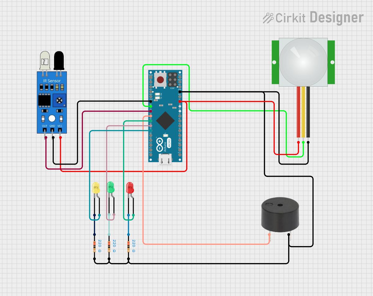
Circuit Documentation
Summary
This document provides a detailed overview of a circuit that includes an Arduino Micro (Rev3) microcontroller, a PIR sensor, an IR sensor, a buzzer, and three LEDs (red, green, and yellow). The circuit is designed to interface with various sensors and output devices, with the Arduino Micro serving as the central control unit.
Component List
Arduino Micro (Rev3)
- Description: A microcontroller board based on the ATmega32U4.
- Pins: MISO, 5V, SCK, MOSI, RESET, GND, RXLED/SS, D1/TX, D0/RX, D2/SDA, D3/SCL, D4 PWM/A6, D5 PWM, D6 PWM/A7, D7, D8 PWM/A8, D9 PWM/A9, D10 PWM/A10, D11 PWM, D12 PWM/A11, VIN, A5, A4, A3, A2, A1, A0, AREF, 3V3, D13 PWM
PIR Sensor
- Description: A passive infrared sensor used to detect motion.
- Pins: VDD, SIG, GND
IR Sensor
- Description: An infrared sensor used to detect objects or measure distance.
- Pins: out, gnd, vcc
Buzzer
- Description: An audio signaling device.
- Pins: PIN, GND
LED: Two Pin (Red)
- Description: A red light-emitting diode.
- Pins: cathode, anode
LED: Two Pin (Green)
- Description: A green light-emitting diode.
- Pins: cathode, anode
LED: Two Pin (Yellow)
- Description: A yellow light-emitting diode.
- Pins: cathode, anode
Resistor (220 Ohms)
- Description: A resistor with a resistance of 220 Ohms.
- Pins: pin1, pin2
Wiring Details
Arduino Micro (Rev3)
- GND is connected to:
- GND of IR sensor
- GND of PIR sensor
- GND of Buzzer (via Resistors)
- D2/SDA is connected to SIG of PIR sensor
- D3/SCL is connected to out of IR sensor
- D4 PWM/A6 is connected to PIN of Buzzer
- D5 PWM is connected to anode of Red LED
- D6 PWM/A7 is connected to anode of Green LED
- D7 is connected to anode of Yellow LED
- 5V is connected to:
- VDD of PIR sensor
- vcc of IR sensor
PIR Sensor
- SIG is connected to D2/SDA of Arduino Micro
- GND is connected to GND of Arduino Micro
- VDD is connected to 5V of Arduino Micro
IR Sensor
- out is connected to D3/SCL of Arduino Micro
- gnd is connected to GND of Arduino Micro
- vcc is connected to 5V of Arduino Micro
Buzzer
- PIN is connected to D4 PWM/A6 of Arduino Micro
- GND is connected to pin2 of Resistor
LED: Two Pin (Red)
- anode is connected to D5 PWM of Arduino Micro
- cathode is connected to pin1 of Resistor
LED: Two Pin (Green)
- anode is connected to D6 PWM/A7 of Arduino Micro
- cathode is connected to pin1 of Resistor
LED: Two Pin (Yellow)
- anode is connected to D7 of Arduino Micro
- cathode is connected to pin1 of Resistor
Resistors
- pin1 of Resistor is connected to:
- cathode of Red LED
- cathode of Green LED
- cathode of Yellow LED
- pin2 of Resistor is connected to:
- GND of Buzzer
- GND of PIR sensor
- GND of Arduino Micro
Code Documentation
Arduino Micro (Rev3) Code
void setup() {
  // put your setup code here, to run once:

}

void loop() {
  // put your main code here, to run repeatedly:

}
This code is a basic template for the Arduino Micro (Rev3). The setup() function is used to initialize any settings or configurations, and the loop() function contains the main logic that runs repeatedly.