
Arduino UNO EMG Sensor-Controlled LCD Display with Piezo Buzzer
View and Edit Project In Cirkit Designer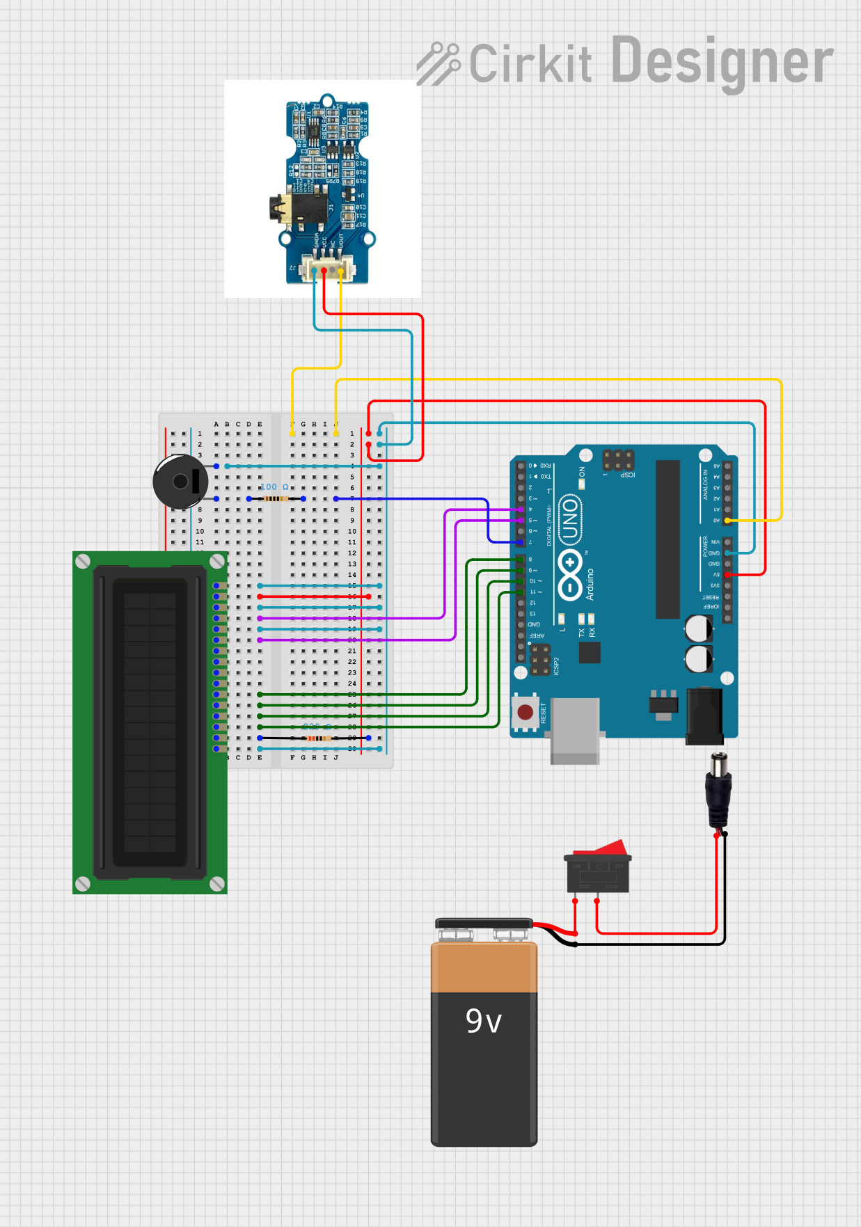
Circuit Documentation
Summary
This circuit involves an Arduino UNO microcontroller interfacing with an LCD Display, a Piezo Buzzer, a Grove EMG Sensor, and a few passive components like resistors and a rocker switch. The circuit is powered by a 9V battery connected through a power jack. The Arduino UNO reads the EMG sensor data and can display information on the LCD. The Piezo Buzzer can be used for audio feedback.
Component List
Arduino UNO
- Description: A microcontroller board based on the ATmega328P.
- Pins: UNUSED, IOREF, Reset, 3.3V, 5V, GND, Vin, A0, A1, A2, A3, A4, A5, SCL, SDA, AREF, D13, D12, D11, D10, D9, D8, D7, D6, D5, D4, D3, D2, D1, D0
LCD Display (16 pin)
- Description: A 16x2 character LCD display.
- Pins: VSS, VDD, VO, RS, R_W, E, DB0, DB1, DB2, DB3, DB4, DB5, DB6, DB7, A, K
Resistor (220 Ohms)
- Description: A resistor with a resistance of 220 Ohms.
- Pins: pin1, pin2
Resistor (100 Ohms)
- Description: A resistor with a resistance of 100 Ohms.
- Pins: pin1, pin2
Piezo Buzzer
- Description: A piezoelectric buzzer for audio output.
- Pins: pin 1, pin 2
Rocker Switch
- Description: A simple on/off switch.
- Pins: 1, 2
9V Battery
- Description: A 9V battery for power supply.
- Pins: -, +
Power Jack
- Description: A power jack for connecting the 9V battery.
- Pins: POSITIF, NEGATIF
Grove EMG Sensor
- Description: An EMG sensor for measuring muscle activity.
- Pins: GND, VCC, NC, VOUT
Wiring Details
Arduino UNO
- A0: Connected to VOUT of Grove EMG Sensor
- GND: Connected to GND of Piezo Buzzer, LCD Display (VSS, VO, R_W, K), and Grove EMG Sensor
- D7: Connected to pin2 of 100 Ohms Resistor
- 5V: Connected to VDD of LCD Display, pin2 of 220 Ohms Resistor, and VCC of Grove EMG Sensor
- D4: Connected to RS of LCD Display
- D5: Connected to E of LCD Display
- D8: Connected to DB4 of LCD Display
- D9: Connected to DB5 of LCD Display
- D10: Connected to DB6 of LCD Display
- D11: Connected to DB7 of LCD Display
LCD Display (16 pin)
- VSS: Connected to GND of Arduino UNO
- VDD: Connected to 5V of Arduino UNO and pin2 of 220 Ohms Resistor
- VO: Connected to GND of Arduino UNO
- RS: Connected to D4 of Arduino UNO
- R_W: Connected to GND of Arduino UNO
- E: Connected to D5 of Arduino UNO
- DB4: Connected to D8 of Arduino UNO
- DB5: Connected to D9 of Arduino UNO
- DB6: Connected to D10 of Arduino UNO
- DB7: Connected to D11 of Arduino UNO
- A: Connected to pin1 of 220 Ohms Resistor
- K: Connected to GND of Arduino UNO
Resistor (220 Ohms)
- pin1: Connected to A of LCD Display
- pin2: Connected to 5V of Arduino UNO and VDD of LCD Display
Resistor (100 Ohms)
- pin1: Connected to pin1 of Piezo Buzzer
- pin2: Connected to D7 of Arduino UNO
Piezo Buzzer
- pin 1: Connected to pin1 of 100 Ohms Resistor
- pin 2: Connected to GND of Arduino UNO
Rocker Switch
- Pin 1: Connected to + of 9V Battery
- Pin 2: Connected to POSITIF of Power Jack
9V Battery
- +: Connected to pin1 of Rocker Switch
- -: Connected to NEGATIF of Power Jack
Power Jack
- POSITIF: Connected to pin2 of Rocker Switch
- NEGATIF: Connected to - of 9V Battery
Grove EMG Sensor
- GND: Connected to GND of Arduino UNO
- VCC: Connected to 5V of Arduino UNO
- VOUT: Connected to A0 of Arduino UNO
Documented Code
Arduino UNO Code (sketch.ino)
void setup() {
  // put your setup code here, to run once:

}

void loop() {
  // put your main code here, to run repeatedly:

}
Documentation (documentation.txt)
This documentation provides a comprehensive overview of the circuit, including a detailed list of components, wiring details, and the code used in the Arduino UNO microcontroller.