
ESP32-Based Health Monitoring System with LCD Display and Buzzer
View and Edit Project In Cirkit Designer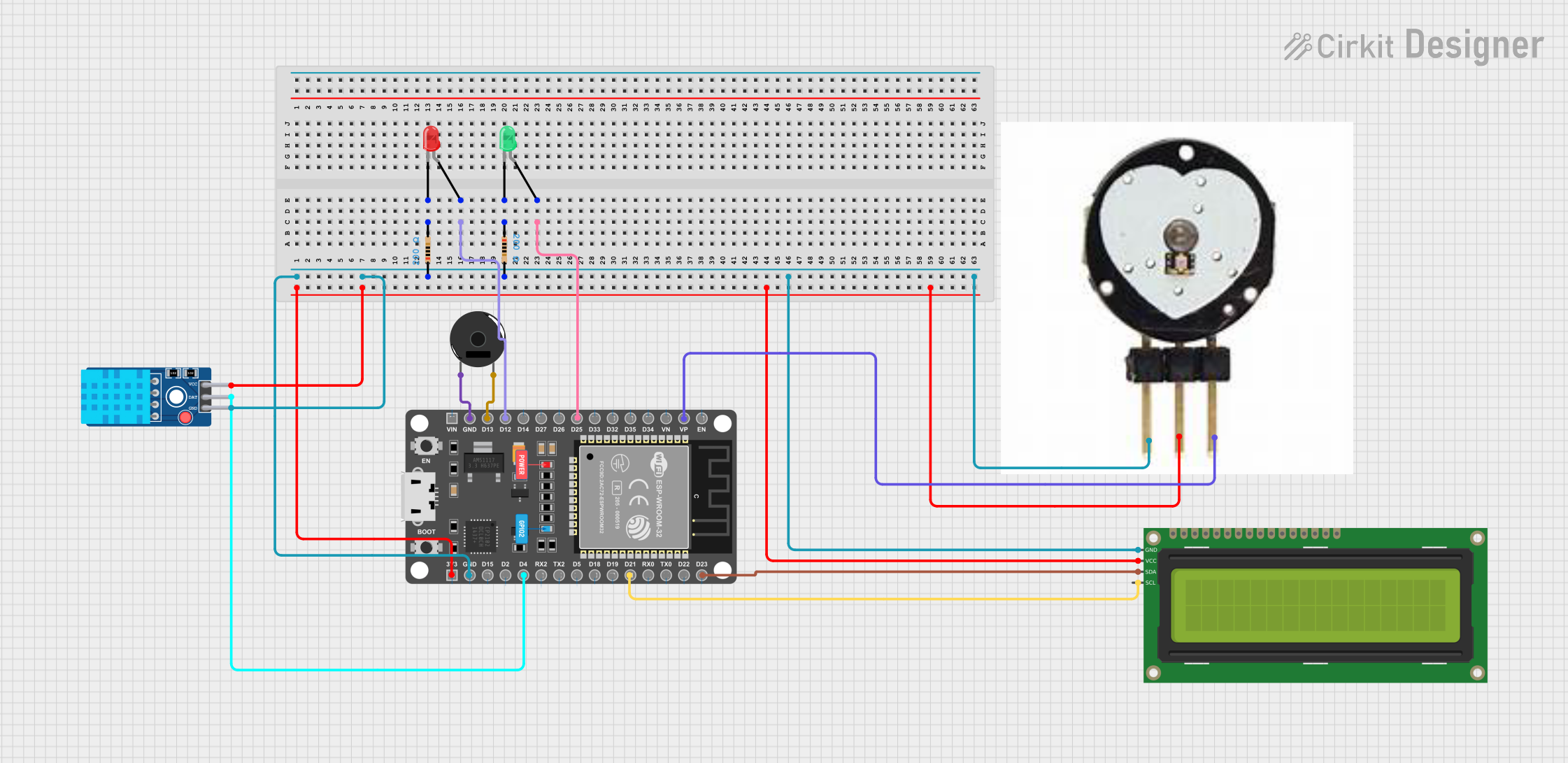
Circuit Documentation
Summary
This document provides a detailed overview of a circuit that includes an ESP32 microcontroller, a piezo buzzer, an I2C LCD display, a DHT11 sensor, a pulse sensor, and two LEDs (red and green) with associated resistors. The circuit is designed to interface various sensors and output devices with the ESP32 for monitoring and display purposes.
Component List
Piezo Buzzer
- Pins: pin 1, pin 2
- Description: A piezoelectric buzzer used for generating sound.
ESP32 DEVKIT V1 (30 pins)
- Pins: EN, VP, VN, D34, D35, D32, D33, D25, D26, D27, D14, D12, D13, GND, VIN, 3V3, D15, D2, D4, RX2, TX2, D5, D18, D19, D21, RX0, TX0, D22, D23
- Description: A development board for the ESP32 microcontroller, featuring multiple GPIO pins and communication interfaces.
16x2 I2C LCD
- Pins: GND, VCC, SDA, SCL
- Description: A 16x2 character LCD display with I2C interface.
DHT11 Sensor V2
- Pins: GND, DAT, VCC
- Description: A digital temperature and humidity sensor.
Pulse Sensor
- Pins: gnd, vcc, ao
- Description: A sensor used to measure heart rate.
LED: Two Pin (red)
- Pins: cathode, anode
- Description: A red LED.
Resistor (200 Ohms)
- Pins: pin1, pin2
- Description: A resistor with a resistance of 200 Ohms.
LED: Two Pin (green)
- Pins: cathode, anode
- Description: A green LED.
Resistor (200 Ohms)
- Pins: pin1, pin2
- Description: A resistor with a resistance of 200 Ohms.
Wiring Details
Piezo Buzzer
- pin 1 connected to GND of ESP32.
- pin 2 connected to D13 of ESP32.
ESP32 DEVKIT V1 (30 pins)
- D12 connected to anode of Red LED.
- D25 connected to anode of Green LED.
- 3V3 connected to VCC of DHT11 Sensor, VCC of I2C LCD, and vcc of Pulse Sensor.
- GND connected to pin1 of Resistor, pin2 of another Resistor, GND of DHT11 Sensor, GND of I2C LCD, gnd of Pulse Sensor, and pin 1 of Piezo Buzzer.
- VP connected to ao of Pulse Sensor.
- D4 connected to DAT of DHT11 Sensor.
- D21 connected to SCL of I2C LCD.
- D23 connected to SDA of I2C LCD.
16x2 I2C LCD
- GND connected to GND of ESP32.
- VCC connected to 3V3 of ESP32.
- SDA connected to D23 of ESP32.
- SCL connected to D21 of ESP32.
DHT11 Sensor V2
- GND connected to GND of ESP32.
- DAT connected to D4 of ESP32.
- VCC connected to 3V3 of ESP32.
Pulse Sensor
- gnd connected to GND of ESP32.
- vcc connected to 3V3 of ESP32.
- ao connected to VP of ESP32.
LED: Two Pin (red)
- cathode connected to pin2 of Resistor.
- anode connected to D12 of ESP32.
Resistor (200 Ohms)
- pin1 connected to GND of ESP32.
- pin2 connected to cathode of Red LED.
LED: Two Pin (green)
- cathode connected to pin1 of another Resistor.
- anode connected to D25 of ESP32.
Resistor (200 Ohms)
- pin1 connected to GND of ESP32.
- pin2 connected to cathode of Green LED.
Code
No code provided for this circuit.
This document provides a comprehensive overview of the circuit, including a detailed list of components and their wiring connections. The ESP32 microcontroller serves as the central unit, interfacing with various sensors and output devices to achieve the desired functionality.