
Raspberry Pi 4B Controlled Robotic Car with Camera and Ultrasonic Sensor
View and Edit Project In Cirkit Designer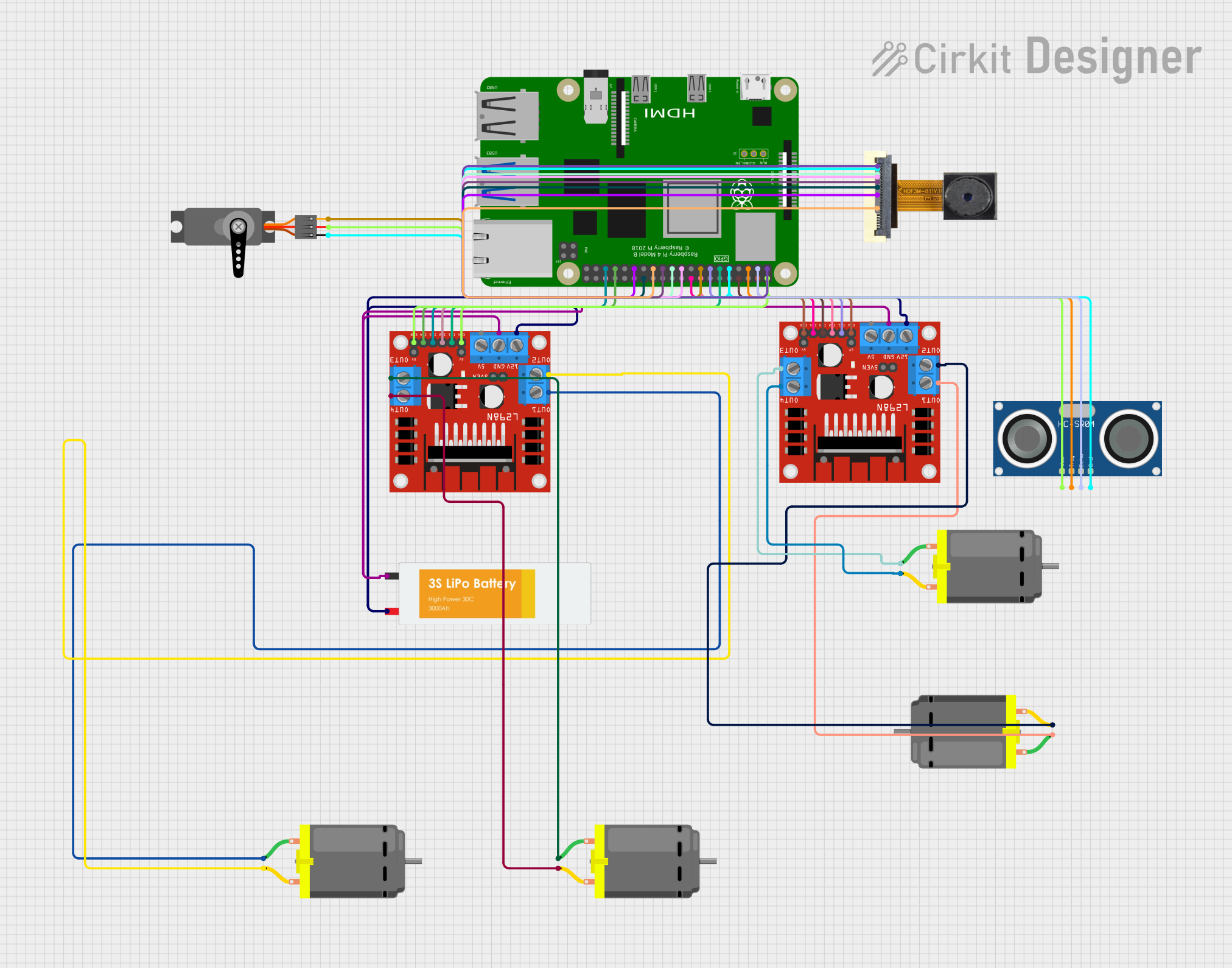
Circuit Documentation
Summary
This document provides a detailed overview of a circuit that includes a Raspberry Pi 4B, multiple DC motors, an L298N DC motor driver, an HC-SR04 Ultrasonic Sensor, an OV2640 Camera Module, a Servo, and a Lipo Battery. The circuit is designed to control the motors and sensors using the Raspberry Pi, which acts as the central processing unit.
Component List
Raspberry Pi 4B
- Description: A powerful single-board computer used for various applications.
- Pins: 3V3, 5V, GPIO2, GPIO3, GND, GPIO4, GPIO14, GPIO15, GPIO17, GPIO18, GPIO27, GPIO22, GPIO23, GPIO24, GPIO10, GPIO9, GPIO25, GPIO11, GPIO8, GPIO7, ID_SD, GPIO5, GPIO6, GPIO12, GPIO13, GPIO19, GPIO16, GPIO26, GPIO20, GPIO21, ID_SC, TR01_TAP, TR00_TAP, TR03_TAP, TR02_TAP, RUN, GLOBAL_EN
DC Motor
- Description: A motor that runs on direct current (DC) electricity.
- Pins: pin 1, pin 2
L298N DC Motor Driver
- Description: A dual H-Bridge motor driver that allows control of two DC motors.
- Pins: OUT1, OUT2, 12V, GND, 5V, OUT3, OUT4, 5V-ENA-JMP-I, 5V-ENA-JMP-O, +5V-J1, +5V-J2, ENA, IN1, IN2, IN3, IN4, ENB
HC-SR04 Ultrasonic Sensor
- Description: A sensor used to measure distance using ultrasonic waves.
- Pins: VCC, TRIG, ECHO, GND
OV2640 Camera Module
- Description: A camera module used for capturing images and videos.
- Pins: 3.3V, GND, SIOC, SIOD, VSync, HRef, PCLK, XCLK, D9, D8, D7, D6, D5, D4, D3, D2, RET, PWDN
Servo
- Description: A motor that allows precise control of angular position.
- Pins: GND, VCC, PWM
Lipo Battery
- Description: A rechargeable lithium polymer battery.
- Pins: VCC, GND
Wiring Details
Raspberry Pi 4B
- 3V3 connected to 3.3V of OV2640 Camera Module
- 5V connected to:
- ENA of L298N DC Motor Driver
- ENB of L298N DC Motor Driver
- VCC of HC-SR04 Ultrasonic Sensor
- VCC of Servo
- GPIO2 connected to ECHO of HC-SR04 Ultrasonic Sensor
- GPIO3 connected to TRIG of HC-SR04 Ultrasonic Sensor
- GPIO14 connected to IN3 of L298N DC Motor Driver
- GND connected to:
- GND of OV2640 Camera Module
- GND of HC-SR04 Ultrasonic Sensor
- GND of Servo
- GPIO17 connected to IN1 of L298N DC Motor Driver
- GPIO27 connected to IN1 of L298N DC Motor Driver
- GPIO22 connected to PWM of Servo
- GPIO23 connected to IN2 of L298N DC Motor Driver
- GPIO24 connected to IN4 of L298N DC Motor Driver
- GPIO10 connected to VSync of OV2640 Camera Module
- GPIO9 connected to SIOD of OV2640 Camera Module
- GPIO11 connected to PCLK of OV2640 Camera Module
- GPIO5 connected to D6 of OV2640 Camera Module
- GPIO13 connected to IN4 of L298N DC Motor Driver
- GPIO19 connected to IN3 of L298N DC Motor Driver
- GPIO16 connected to IN2 of L298N DC Motor Driver
- ID_SC connected to D9 of OV2640 Camera Module
DC Motor
- pin 1 connected to OUT1 of L298N DC Motor Driver
- pin 2 connected to OUT2 of L298N DC Motor Driver
L298N DC Motor Driver
- OUT1 connected to pin 1 of DC Motor
- OUT2 connected to pin 2 of DC Motor
- OUT3 connected to pin 1 of another DC Motor
- OUT4 connected to pin 2 of another DC Motor
- 12V connected to VCC of Lipo Battery
- GND connected to GND of Lipo Battery
HC-SR04 Ultrasonic Sensor
- VCC connected to 5V of Raspberry Pi 4B
- TRIG connected to GPIO3 of Raspberry Pi 4B
- ECHO connected to GPIO2 of Raspberry Pi 4B
- GND connected to GND of Raspberry Pi 4B
OV2640 Camera Module
- 3.3V connected to 3V3 of Raspberry Pi 4B
- GND connected to GND of Raspberry Pi 4B
- VSync connected to GPIO10 of Raspberry Pi 4B
- SIOD connected to GPIO9 of Raspberry Pi 4B
- PCLK connected to GPIO11 of Raspberry Pi 4B
- D6 connected to GPIO5 of Raspberry Pi 4B
- D9 connected to ID_SC of Raspberry Pi 4B
Servo
- GND connected to GND of Raspberry Pi 4B
- VCC connected to 5V of Raspberry Pi 4B
- PWM connected to GPIO22 of Raspberry Pi 4B
Lipo Battery
- VCC connected to 12V of L298N DC Motor Driver
- GND connected to GND of L298N DC Motor Driver
Code
No code is provided for this circuit.
This document provides a comprehensive overview of the circuit, including a summary, component list, wiring details, and code section. Each component is described, and the wiring details are provided to ensure proper connections.