ESP8266 NodeMCU Controlled GPS Tracker with Relay-Activated Gearmotor
Circuit Documentation
Summary
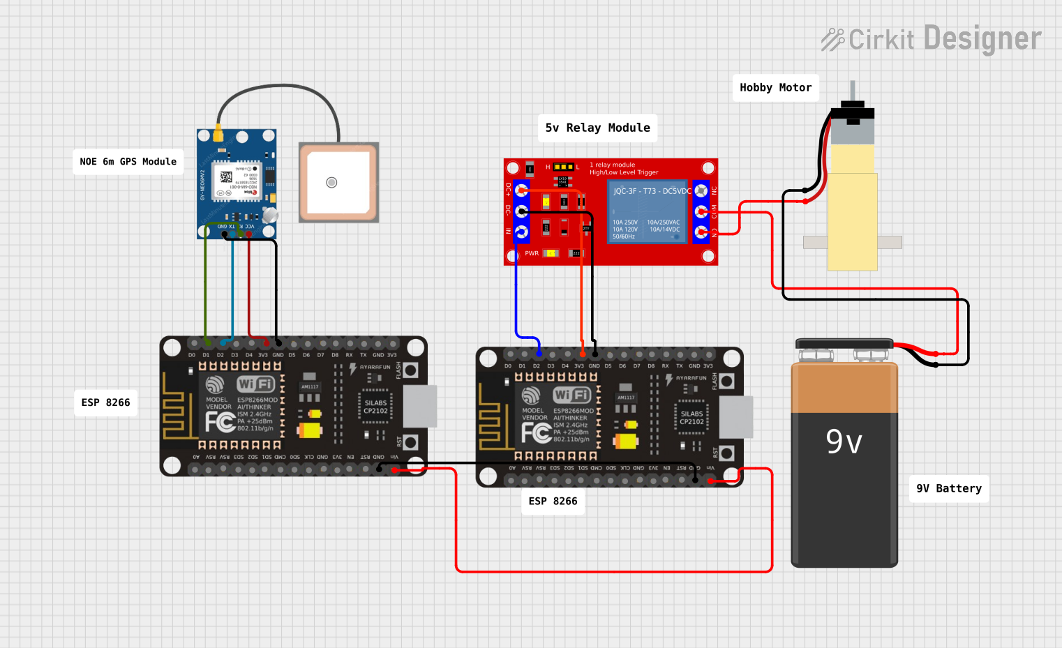
This circuit integrates a GPS module, an ESP8266 NodeMCU microcontroller, a 5V relay module, and a hobby gearmotor to form a GPS-controlled actuator system. The ESP8266 NodeMCU is used as the central processing unit, interfacing with the GPS module for location data and controlling the relay module, which in turn drives the gearmotor. The system is powered by a 9V battery, with voltage regulation provided by the NodeMCU's onboard voltage regulator.
Component List
GPS NEO 6M
- Description: A GPS module capable of providing geolocation data.
- Pins: VCC, RX, TX, GND
ESP8266 NodeMCU
- Description: A Wi-Fi enabled microcontroller with a variety of digital and analog pins for interfacing with various sensors and actuators.
- Pins: D0, D1, D2, D3, D4, 3V3, GND, D5, D6, D7, D8, RX, TX, A0, RSV, SD3, SD2, SD1, CMD, SD0, CLK, EN, RST, VIN
1 Channel 5V Relay Module
- Description: An electromechanical switch that allows a low-power signal to control a higher power circuit, in this case, the gearmotor.
- Pins: VCC+, VCC- (GND), IN, N.O., COM, N.C.
Hobby Gearmotor with 48:1 Gearbox
- Description: A DC motor with a gearbox for increased torque, used as the actuator in this circuit.
- Pins: pin 1, pin 2
9V Battery
- Description: Provides power to the circuit.
- Pins: -, +
Wiring Details
GPS NEO 6M
- VCC: Connected to 3V3 on ESP8266 NodeMCU
- RX: Connected to D1 on ESP8266 NodeMCU
- TX: Connected to D2 on ESP8266 NodeMCU
- GND: Connected to GND on ESP8266 NodeMCU
ESP8266 NodeMCU
- 3V3: Powers the GPS NEO 6M and the 1 Channel 5V Relay Module
- GND: Common ground for the GPS NEO 6M, Relay Module, and the other NodeMCU
- D1: Receives TX from GPS NEO 6M
- D2: Connected to RX on GPS NEO 6M and IN on Relay Module
- VIN: Connected to VIN on the other NodeMCU for power distribution
1 Channel 5V Relay Module
- VCC+: Connected to 3V3 on ESP8266 NodeMCU
- VCC- (GND): Connected to GND on ESP8266 NodeMCU
- IN: Connected to D2 on ESP8266 NodeMCU
- N.O.: Connected to pin 2 on Hobby Gearmotor
- COM: Connected to + on 9V Battery
Hobby Gearmotor with 48:1 Gearbox
- pin 1: Connected to - on 9V Battery
- pin 2: Connected to N.O. on Relay Module
9V Battery
- +: Connected to COM on Relay Module
- -: Connected to pin 1 on Hobby Gearmotor
Documented Code
No code was provided for the microcontrollers in the circuit. To fully utilize the hardware, embedded code should be written and uploaded to the ESP8266 NodeMCU microcontrollers. The code should initialize the GPS module, read location data, and based on the received data, control the relay module to drive the gearmotor.