Raspberry Pi 4B Controlled LIDAR and Dual Motor System with Visual and Audio Indicators
Circuit Documentation
Summary
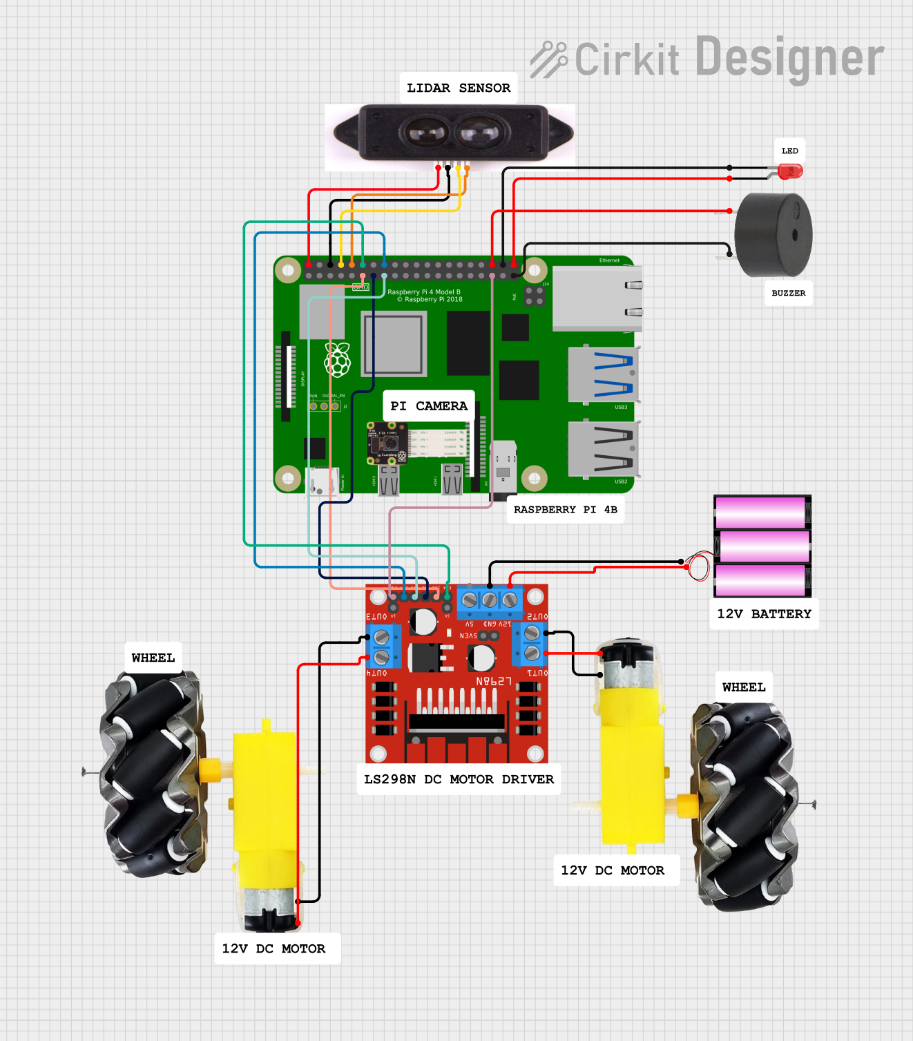
The circuit in question is designed to interface a Raspberry Pi 4B with a LIDAR sensor, a L298N DC motor driver, a pair of motors with wheels, a 12V battery, an LED, and a buzzer. The Raspberry Pi 4B serves as the central processing unit, controlling the LIDAR for distance measurement, driving the motors via the motor driver, and providing feedback to the user through the LED and buzzer. The 12V battery powers the motor driver, which in turn controls the motors. The LED and buzzer are used for visual and audible signals, respectively.
Component List
Raspberry Pi 4B
- Description: A small single-board computer with GPIO pins for interfacing with various electronic components.
- Pins: 3V3, 5V, multiple GPIOs, GND, and others for specific functions.
LIDAR
- Description: A sensor used for measuring distances using laser light.
- Pins: VCC, GND, RDX, TDX.
L298N DC Motor Driver
- Description: A module used for controlling the direction and speed of DC motors.
- Pins: OUT1, OUT2, 12V, GND, 5V, OUT3, OUT4, ENA, IN1, IN2, IN3, IN4, ENB.
Motor and Wheels (2 instances)
- Description: A set of motors attached to wheels, used for providing motion to the system.
- Pins: vcc, GND.
Battery 12V
- Description: A power source used to supply the motor driver and, indirectly, the motors.
- Pins: +, -.
LED: Two Pin (red)
- Description: A red LED used for visual indication.
- Pins: cathode, anode.
Buzzer
- Description: An audible signaling device.
- Pins: PIN, GND.
Wiring Details
Raspberry Pi 4B
- 5V connected to LIDAR VCC.
- GND connected to LIDAR GND, buzzer GND.
- GPIO14 (TXD) connected to LIDAR RDX.
- GPIO15 (RXD) connected to LIDAR TDX.
- GPIO17 connected to L298N DC motor driver IN1.
- GPIO18 connected to L298N DC motor driver ENA.
- GPIO27 connected to L298N DC motor driver IN2.
- GPIO22 connected to L298N DC motor driver IN3.
- GPIO23 connected to L298N DC motor driver IN4.
- GPIO19 connected to L298N DC motor driver ENB.
- GPIO16 connected to buzzer PIN.
- GPIO20 connected to LED cathode.
- GPIO21 connected to LED anode.
LIDAR
- VCC connected to Raspberry Pi 4B 5V.
- GND connected to Raspberry Pi 4B GND.
- RDX connected to Raspberry Pi 4B GPIO14.
- TDX connected to Raspberry Pi 4B GPIO15.
L298N DC Motor Driver
- OUT1 connected to motor and wheels vcc.
- OUT2 connected to motor and wheels GND.
- 12V connected to battery 12V +.
- GND connected to battery 12V -.
- IN1 connected to Raspberry Pi 4B GPIO17.
- ENA connected to Raspberry Pi 4B GPIO18.
- IN2 connected to Raspberry Pi 4B GPIO27.
- IN3 connected to Raspberry Pi 4B GPIO22.
- IN4 connected to Raspberry Pi 4B GPIO23.
- ENB connected to Raspberry Pi 4B GPIO19.
- OUT3 connected to second motor and wheels GND.
- OUT4 connected to second motor and wheels vcc.
Motor and Wheels
- vcc connected to L298N DC motor driver OUT1/OUT4.
- GND connected to L298N DC motor driver OUT2/OUT3.
Battery 12V
- connected to L298N DC motor driver 12V.
- connected to L298N DC motor driver GND.
LED: Two Pin (red)
- cathode connected to Raspberry Pi 4B GPIO20.
- anode connected to Raspberry Pi 4B GPIO21.
Buzzer
- PIN connected to Raspberry Pi 4B GPIO16.
- GND connected to Raspberry Pi 4B GND.
Documented Code
No code was provided for the microcontrollers in the circuit. The Raspberry Pi 4B would typically be programmed to control the LIDAR sensor, motor driver, LED, and buzzer. The code would include initializing the GPIO pins, setting up serial communication with the LIDAR, and implementing control algorithms for the motors. It would also handle the logic for turning on the LED and activating the buzzer under certain conditions. Since no code is available, this section cannot be completed.