Arduino-Controlled Obstacle-Avoiding Robot with Ultrasonic Sensor and Servo Motor
Circuit Documentation
Summary
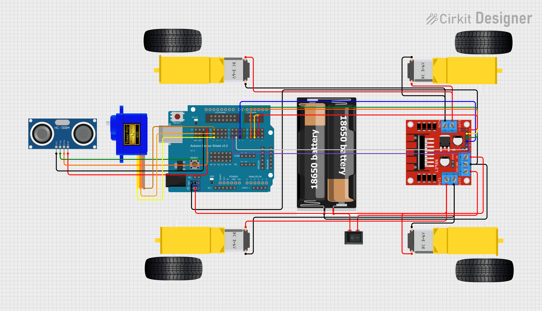
The circuit in question appears to be designed for a mobile robot platform equipped with an Arduino UNO as the main controller, an ultrasonic sensor for distance measurement, DC gearmotors for movement, a servomotor for directional control, an L298N motor driver for controlling the gearmotors, a power supply consisting of two 18650 batteries, and a rocker switch for power management. The Arduino UNO is extended with a Sensor Shield v5.0 to facilitate easy connections to various sensors and actuators.
Component List
Arduino UNO
- Microcontroller board based on the ATmega328P
- It has 14 digital input/output pins, 6 analog inputs, a 16 MHz quartz crystal, a USB connection, a power jack, an ICSP header, and a reset button.
HC-SR04 Ultrasonic Sensor
- Ultrasonic distance sensor
- Provides 2cm to 400cm non-contact measurement functionality with a ranging accuracy that can reach up to 3mm.
Gearmotor DC Wheels (Left and Right)
- DC motors with gear reduction
- Used for driving the wheels of the robot.
Servomotor SG90
- Small and lightweight servo motor
- Capable of rotating approximately 180 degrees (90 in each direction).
L298N DC Motor Driver
- Dual H-Bridge motor driver
- Can drive two DC motors or one stepper motor.
Rocker Switch (SPST)
- Single Pole Single Throw (SPST) switch
- Used to control the power supply to the circuit.
Arduino Sensor Shield v5.0
- Expansion board for Arduino
- Allows for easy connection of various components to the Arduino without the need for soldering.
2x 18650 Batteries
- Rechargeable lithium-ion batteries
- Provide power to the circuit.
Wiring Details
Arduino UNO
- Utilizes the Sensor Shield v5.0 for connections to other components.
HC-SR04 Ultrasonic Sensor
- VCC connected to 5V on the Sensor Shield
- TRIG connected to digital pin 13 on the Sensor Shield
- ECHO connected to digital pin 12 on the Sensor Shield
- GND connected to GND on the Sensor Shield
Gearmotors (Left and Right)
- Controlled by the L298N motor driver
- Connections are made from the motor driver outputs to the motors.
Servomotor SG90
- SIG connected to digital pin 11 on the Sensor Shield
- VCC connected to 5V on the Sensor Shield
- GND connected to GND on the Sensor Shield
L298N DC Motor Driver
- OUT1, OUT2, OUT3, and OUT4 connected to the gearmotors
- 12V input connected through the Rocker Switch to the 18650 batteries
- 5V output connected to 5V on the Sensor Shield
- GND connected to GND on the Sensor Shield
- ENA, ENB, IN1, IN2, IN3, and IN4 connected to corresponding digital pins on the Sensor Shield
Rocker Switch (SPST)
- One side connected to the positive terminal of the 18650 batteries
- The other side connected to the 12V input of the L298N motor driver
2x 18650 Batteries
- VCC connected to the Rocker Switch
- GND connected to GND on the Sensor Shield
Documented Code
#include <Servo.h>

volatile int IN1 = 11;
volatile int IN2 = 6;
volatile int IN3 = 5;
volatile int IN4 = 3;
volatile int rightDistance;
volatile int leftDistance;
Servo servo_4;

void left_side_forward(int speed) {
  analogWrite(IN1, speed * 0.92);
  analogWrite(IN2, 0);
}

void right_side_forward(int speed) {
  analogWrite(IN3, speed);
  analogWrite(IN4, 0);
}

void left_side_backward(int speed) {
  analogWrite(IN1, 0);
  analogWrite(IN2, speed * 0.92);
}

void right_side_backward(int speed) {
  analogWrite(IN3, 0);
  analogWrite(IN4, speed);
}

float checkdistance_A1_A2() {
  digitalWrite(A1, LOW);
  delayMicroseconds(2);
  digitalWrite(A1, HIGH);
  delayMicroseconds(10);
  digitalWrite(A1, LOW);
  float distance = pulseIn(A2, HIGH) / 58.00;
  delay(10);
  return distance;
}

void forward(int speed) {
  left_side_forward(speed);
  right_side_forward(speed);
}

void backward(int speed) {
  left_side_backward(speed);
  right_side_backward(speed);
}

void left(int speed, int time) {
  left_side_backward(speed);
  right_side_forward(speed);
  delay(time);
  stop();
}

void right(int speed, int time) {
  left_side_forward(speed);
  right_side_backward(speed);
  delay(time);
  stop();
}

void stop() {
  left_side_forward(0);
  right_side_forward(0);
}

void setup() {
  servo_4.attach(4);
  pinMode(A1, OUTPUT);
  pinMode(A2, INPUT);
  pinMode(IN1, OUTPUT);
  pinMode(IN2, OUTPUT);
  pinMode(IN3, OUTPUT);
  pinMode(IN4, OUTPUT);
}

void loop() {
  servo_4.write(90);
  delay(200); // Reduce delay for better responsiveness

  float distance = checkdistance_A1_A2();
  while (distance > 15) {
    forward(150); // Increase speed for faster response
    distance = checkdistance_A1_A2(); // Continuously update distance
  }
  stop();
  delay(100); // Reduce delay for better responsiveness

  servo_4.write(0);
  delay(200); // Reduce delay for better responsiveness
  rightDistance = checkdistance_A1_A2();

  servo_4.write(180);
  delay(200); // Reduce delay for better responsiveness
  leftDistance = checkdistance_A1_A2();

  if (rightDistance >= leftDistance) {
    right(200, 300); // Reduce rotation time for more precision
  } else {
    left(200, 300); // Reduce rotation time for more precision
  }
}
This code is designed to control a robot with differential steering. It uses an ultrasonic sensor to avoid obstacles by checking distances and steering the robot accordingly. The servomotor is used to change the direction of the ultrasonic sensor for scanning the environment. The L298N motor driver controls the gearmotors for movement. The code includes functions for moving forward, backward, stopping, and turning left or right. The setup function initializes the pins, and the loop function contains the main logic for obstacle avoidance and movement.