
ESP32-Controlled Multi-Color LED Array with GSM and GPS Functionality
View and Edit Project In Cirkit Designer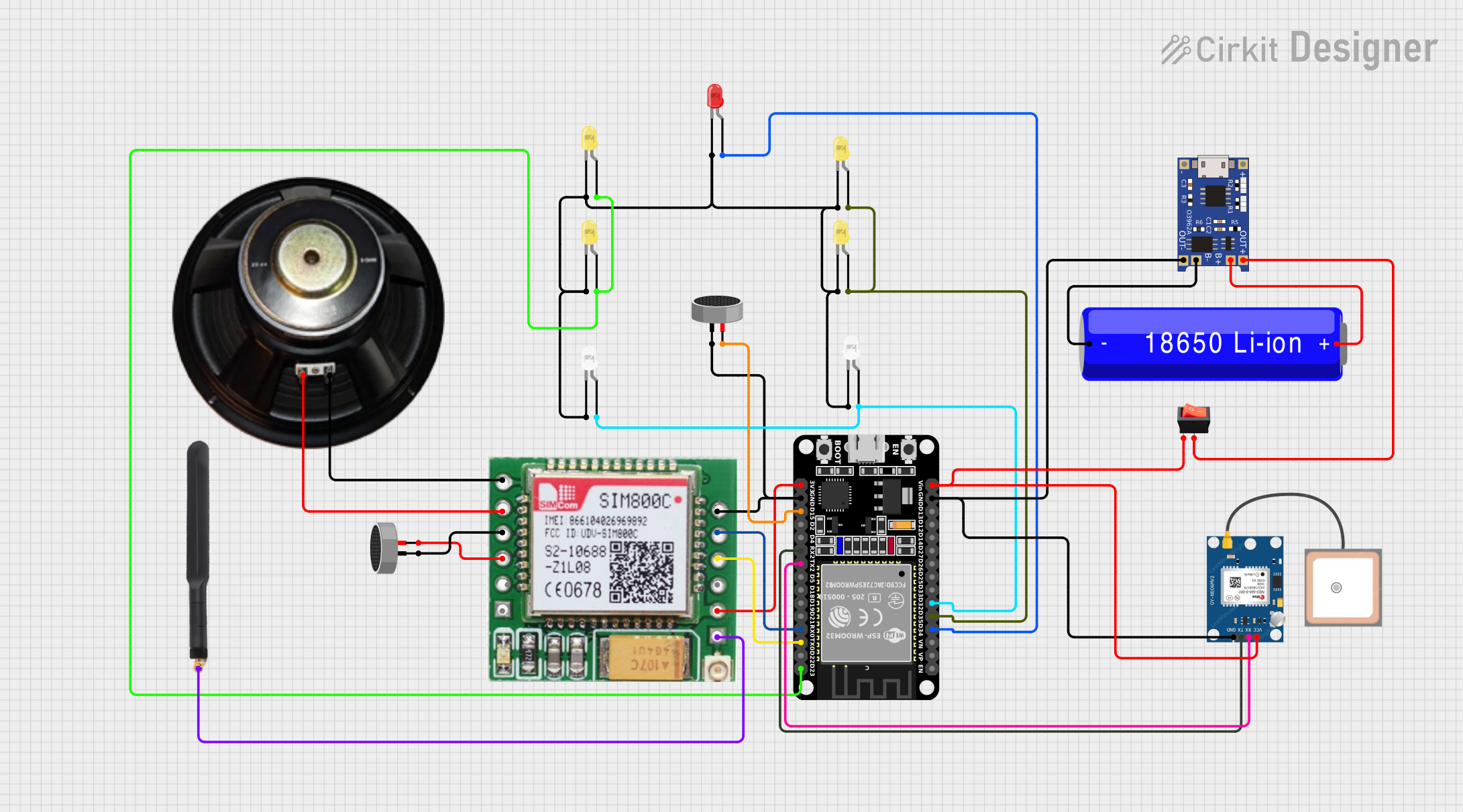
Circuit Documentation
Summary
The circuit in question appears to be a communication and signaling device that utilizes an ESP32 microcontroller to control multiple LEDs and interface with a SIM800c GSM module for cellular communication capabilities. It also includes a GPS module (NEO 6M) for location tracking, a speaker and condenser microphone for audio input and output, and a TP4056 module for charging an 18650 Li-ion battery which powers the system. A rocker switch is used to control the power supply to the circuit.
Component List
LEDs
- Red LED: A two-pin light-emitting diode that emits red light.
- Yellow LEDs: Two-pin light-emitting diodes that emit yellow light.
- White LEDs: Two-pin light-emitting diodes that emit white light.
Communication Modules
- SIM800c GSM Module: A module that provides GSM/GPRS communication.
- GPS NEO 6M: A module for receiving GPS signals and determining the location.
Microcontroller
- ESP32 (30 pin): A microcontroller with Wi-Fi and Bluetooth capabilities, featuring a variety of digital and analog pins.
Audio Components
- Speaker: An audio output device.
- Condenser Microphones: Audio input devices that capture sound.
Antenna
- 4G Antenna: An antenna for enhancing cellular signal reception.
Power Management
- TP4056: A charging module for lithium-ion batteries.
- 18650 Li-ion Battery: A rechargeable battery providing power to the circuit.
- Rocker Switch: A switch to control the power flow in the circuit.
Wiring Details
LEDs
- Red LED: Cathode connected to common cathode net, anode connected to ESP32 pin D34.
- Yellow LEDs: Cathodes connected to common cathode net, anodes connected to ESP32 pins D35, D23, and others not specified.
- White LEDs: Cathodes connected to common cathode net, anodes connected to ESP32 pin D32.
Communication Modules
- SIM800c GSM Module:
- Speaker connections: SPK- to Speaker (-), SPK+ to Speaker (+).
- Microphone connections: MIC- to Condenser Microphone pin1, MIC+ to Condenser Microphone pin2.
- Serial connections: TXD to ESP32 RX0, RXD to ESP32 TX0.
- Power connections: VCC to ESP32 3V3, GND to common ground net.
- Antenna connection: ANT to 4G Antenna Connection.
- GPS NEO 6M:
- Serial connections: RX to ESP32 TX2, TX to ESP32 RX2.
- Power connections: VCC to rocker switch output, GND to common ground net.
Microcontroller
- ESP32 (30 pin):
- Digital pins D34, D35, D23, D32 connected to various LED anodes.
- Serial communication pins RX0, TX0 connected to SIM800c GSM Module.
- Serial communication pins RX2, TX2 connected to GPS NEO 6M.
- Power pins 3V3, Vin connected to SIM800c GSM Module and rocker switch respectively.
- Ground pin GND connected to common ground net.
Audio Components
- Speaker: Connected to SIM800c GSM Module speaker pins.
- Condenser Microphones: Connected to SIM800c GSM Module microphone pins and ESP32 pin D15.
Power Management
- TP4056:
- Battery connections: B- to 18650 Li-ion Battery (-), B+ to 18650 Li-ion Battery (+).
- Output connections: OUT- to common ground net, OUT+ to rocker switch input.
- 18650 Li-ion Battery:
- Connected to TP4056 B- and B+ for charging.
- Rocker Switch:
- Input connected to TP4056 OUT+, output connected to GPS NEO 6M VCC and ESP32 Vin.
Documented Code
No code has been provided for the microcontroller. The documentation of the code would typically include details on the initialization of peripherals, the main control loop, interrupt service routines, and any communication protocols implemented. Since no code is available, this section cannot be completed.