NodeMCU-Based Metal Detection System with OLED Feedback and Servo Actuation
Circuit Documentation
Summary
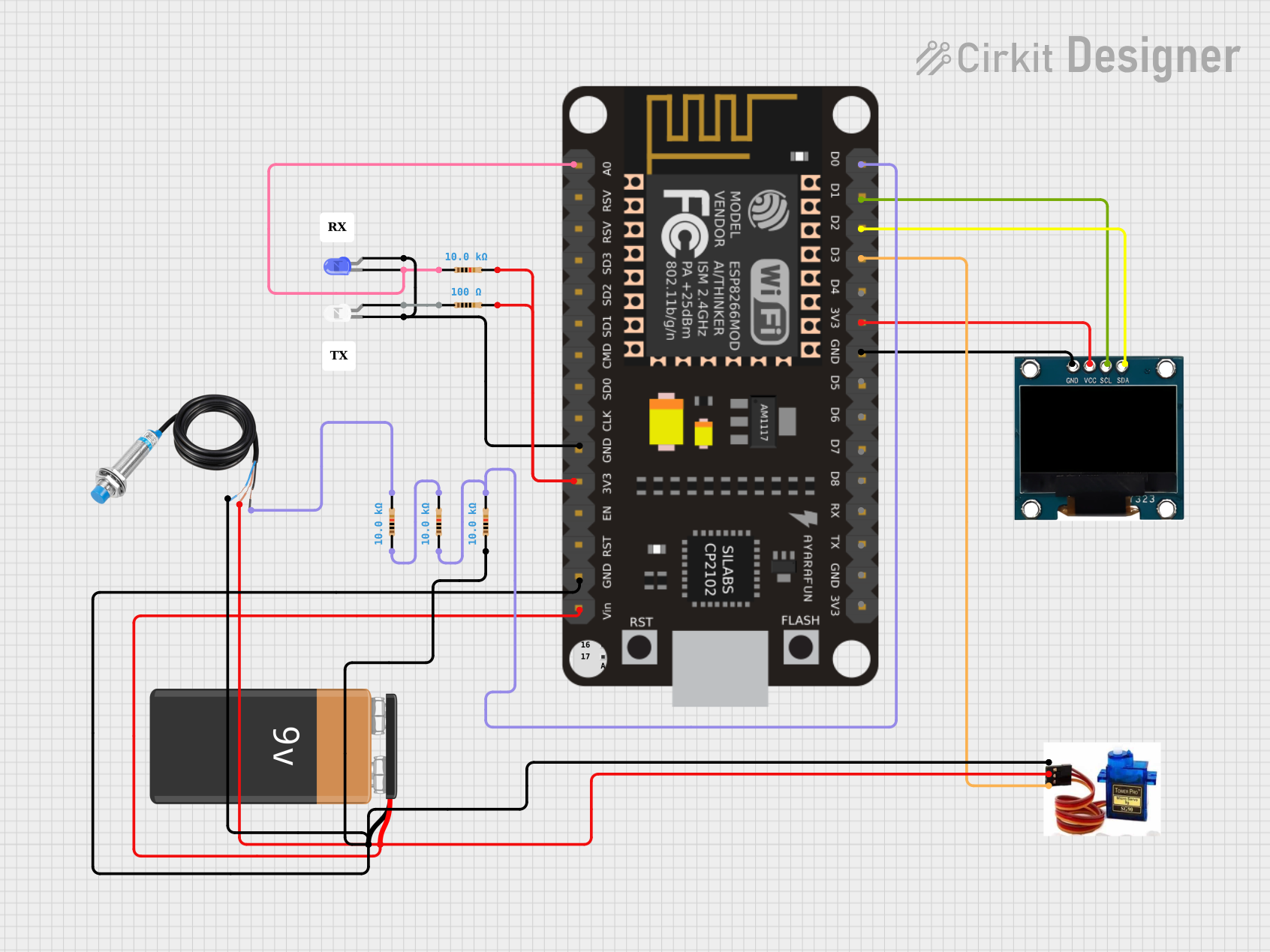
This circuit integrates a NodeMCU microcontroller with an OLED display, a metal detection sensor, a servo motor, two LEDs (white and blue), and several resistors. The circuit is powered by a 9V battery. The NodeMCU facilitates communication with the OLED display via I2C protocol and controls the servo motor. It also reads the output from the metal detection sensor and drives the LEDs based on certain conditions. The resistors are used for current limiting and pull-down configurations.
Component List
NodeMCU
- Description: A microcontroller board based on the ESP8266 chip, featuring Wi-Fi capabilities and multiple digital and analog pins.
- Pins: D0, D1, D2, D3, D4, 3.3v, GND, 5V, A0, 3.3V, D5, D6, D7, D8, RX, TX
OLED 4 Pin
- Description: A small organic light-emitting diode display module with I2C interface.
- Pins: GND, VCC, SCL, SDA
Metal Detection Sensor
- Description: A sensor capable of detecting metallic objects.
- Pins: POWER, GND, OUT
9V Battery
- Description: A standard 9V battery used to power the circuit.
- Pins: -, +
Resistors (10k Ohms)
- Description: Passive electrical components used to limit current or divide voltages.
- Resistance: 10,000 Ohms
Resistors (100 Ohms)
- Description: Passive electrical components used to limit current or divide voltages.
- Resistance: 100 Ohms
LED: Two Pin (White)
- Description: A white light-emitting diode used as an indicator.
- Pins: Cathode, Anode
LED: Two Pin (Blue)
- Description: A blue light-emitting diode used as an indicator.
- Pins: Cathode, Anode
Servo Motor SG90
- Description: A small and lightweight servo motor used for precise angular movement.
- Pins: GND, VCC, SIG
Wiring Details
NodeMCU
- D0 connected to a 10k Ohm resistor
- D1 (SCL) connected to OLED SCL
- D2 (SDA) connected to OLED SDA
- D3 connected to Servo Motor SIG
- 3.3v connected to OLED VCC
- GND connected to OLED GND, Servo Motor GND, and the cathodes of both LEDs
- 5V connected to the 9V Battery, Servo Motor VCC, and Metal Detection Sensor POWER
- A0 connected to a 10k Ohm resistor and the cathode of the blue LED
OLED 4 Pin
- SCL connected to NodeMCU D1
- SDA connected to NodeMCU D2
- VCC connected to NodeMCU 3.3v
- GND connected to NodeMCU GND
Metal Detection Sensor
- POWER connected to 9V Battery and Servo Motor VCC
- GND connected to a 10k Ohm resistor and NodeMCU GND
- OUT connected to a 10k Ohm resistor
9V Battery
- connected to NodeMCU 5V, Servo Motor VCC, and Metal Detection Sensor POWER
- connected to Servo Motor GND and NodeMCU GND
Resistors (10k Ohms)
- One end connected to NodeMCU D0, the other end connected to another 10k Ohm resistor
- One end connected to Metal Detection Sensor OUT, the other end connected to another 10k Ohm resistor
- One end connected to NodeMCU A0, the other end connected to the cathode of the blue LED
- One end connected to Metal Detection Sensor GND, the other end connected to NodeMCU GND
Resistors (100 Ohms)
- One end connected to NodeMCU 3.3V, the other end connected to a 10k Ohm resistor and the anode of the white LED
LED: Two Pin (White)
- Cathode connected to NodeMCU GND
- Anode connected to a 100 Ohm resistor
LED: Two Pin (Blue)
- Cathode connected to a 10k Ohm resistor
- Anode connected to NodeMCU GND
Servo Motor SG90
- GND connected to 9V Battery - and NodeMCU GND
- VCC connected to 9V Battery + and Metal Detection Sensor POWER
- SIG connected to NodeMCU D3
Documented Code
No code has been provided for the microcontroller. The documentation of the code would typically include a description of the functionality, setup and loop functions, and any functions or libraries used to control the components in the circuit. Since no code is available, this section cannot be completed.