
Arduino-Based Biometric Security System with GPS and GSM Integration
View and Edit Project In Cirkit Designer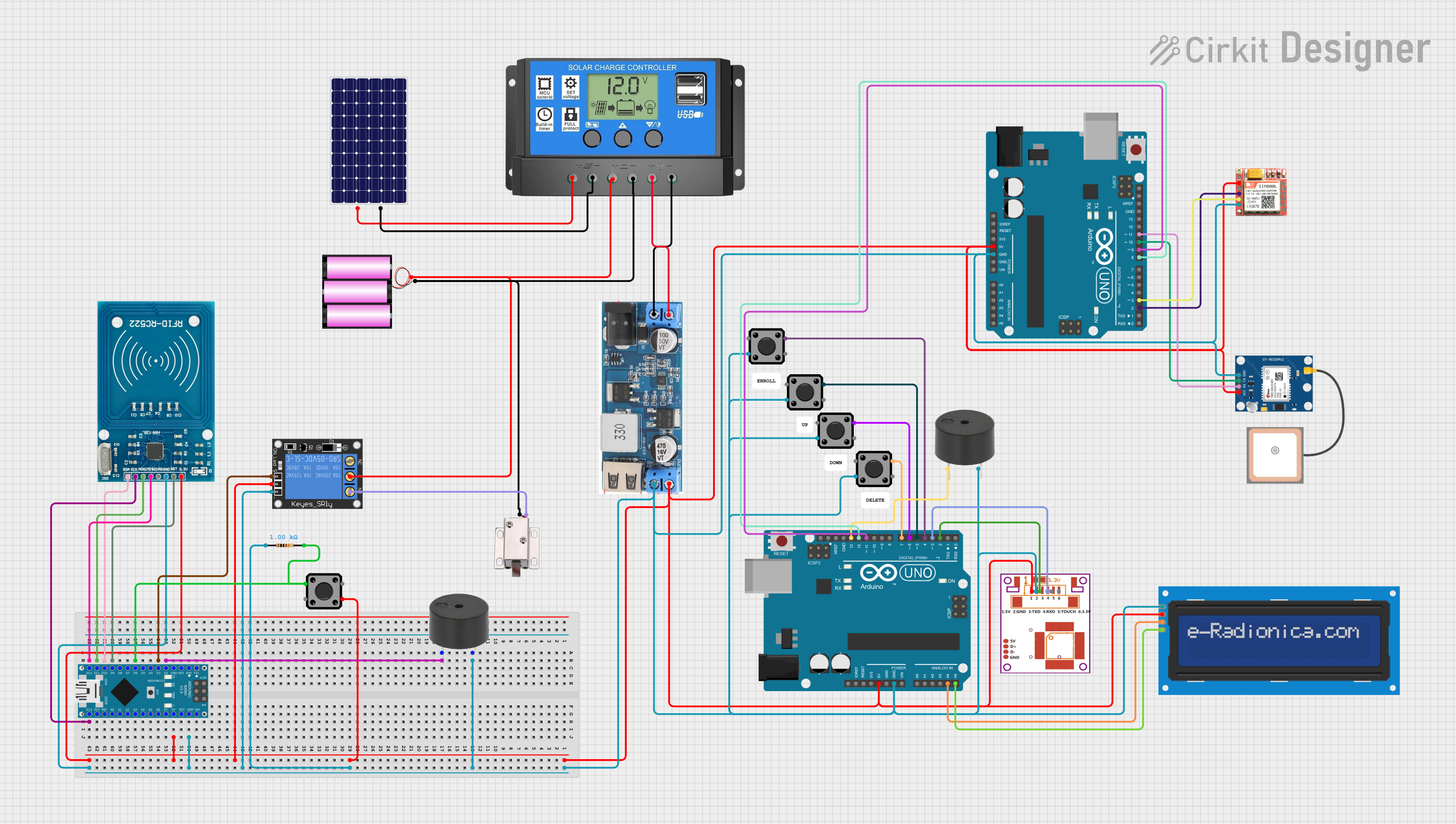
Circuit Documentation
Summary
This circuit is a biometric security system that integrates various components such as an Arduino UNO, Arduino Nano, fingerprint sensor, RFID module, GPS module, GSM module, LCD screen, tactile switches, buzzers, a solenoid lock, and a solar power system. The system is designed to control access using fingerprint recognition and RFID, and it can send location data via SMS using the GPS and GSM modules. The circuit is powered by a combination of a solar panel and a 12V battery, managed by a solar charge controller.
Component List
1. Battery 12V
- Description: Provides 12V power supply.
- Pins: +, -
2. Tactile Switch Buttons - 12mm Square
- Description: Used for user input.
- Pins: 3, 1, 4, 2
3. Resistor
- Description: Limits current flow.
- Pins: pin1, pin2
- Properties: 1000 Ohms
4. Arduino UNO
- Description: Main microcontroller for the system.
- Pins: UNUSED, IOREF, Reset, 3.3V, 5V, GND, Vin, A0, A1, A2, A3, A4, A5, SCL, SDA, AREF, D13, D12, D11, D10, D9, D8, D7, D6, D5, D4, D3, D2, D1, D0
5. 12V Solenoid Lock
- Description: Controls physical access.
- Pins: VCC, GND
6. Solar Panel
- Description: Provides renewable energy.
- Pins: +, -
7. R307 Fingerprint Sensor
- Description: Captures and verifies fingerprints.
- Pins: VCC, GND, TX, RX, Touch, 3.3V
8. RFID-RC522
- Description: Reads RFID tags.
- Pins: VCC (3.3V), RST, GND, IRQ, MISO, MOSI, SCK, SDA
9. GPS NEO 6M
- Description: Provides GPS data.
- Pins: VCC, RX, TX, GND
10. LCD Screen 16x2 I2C
- Description: Displays information.
- Pins: SCL, SDA, VCC, GND
11. Buzzer
- Description: Provides audio feedback.
- Pins: PIN, GND
12. SIM 800L
- Description: GSM module for communication.
- Pins: NFT, RING, VCC, DTR, RST, MIC +, RXD, MIC-, TXD, SPK+, GND, SPK-
13. 1-Channel Relay (5V 10A)
- Description: Controls high-power devices.
- Pins: NC, signal, C, power, NO, ground
14. Solar Charge Controller
- Description: Manages solar power and battery charging.
- Pins: Solar Cell +, Solar Cell -, Battery +, Battery -, Load +, Load -
15. DCDC 12V/5V 3A
- Description: Converts 12V to 5V.
- Pins: 12V (+), GND, 5V (+), Vin (+), V in (-)
16. Arduino Nano
- Description: Secondary microcontroller for the system.
- Pins: D1/TX, D0/RX, RESET, GND, D2, D3, D4, D5, D6, D7, D8, D9, D10, D11/MOSI, D12/MISO, VIN, 5V, A7, A6, A5, A4, A3, A2, A1, A0, AREF, 3V3, D13/SCK
Wiring Details
Battery 12V
- +: Connected to Solar Charge Controller (Battery +)
- -: Connected to Solar Charge Controller (Battery -) and 12V Solenoid Lock (GND)
Tactile Switch Buttons - 12mm Square
- 3: Connected to Arduino UNO (5V)
- 1: Connected to Arduino UNO (D4, D5, D6, D7)
- 4: Connected to GND
- 2: Connected to Arduino Nano (D6) and Resistor (pin2)
Resistor
- pin1: Connected to GND
- pin2: Connected to Tactile Switch Buttons (2) and Arduino Nano (D6)
Arduino UNO
- GND: Connected to GND
- 5V: Connected to 5V power supply
- A4: Connected to LCD Screen (SDA)
- A5: Connected to LCD Screen (SCL)
- D2: Connected to R307 Fingerprint Sensor (TX)
- D3: Connected to R307 Fingerprint Sensor (RX)
- D4: Connected to Tactile Switch Buttons (1)
- D5: Connected to Tactile Switch Buttons (1)
- D6: Connected to Tactile Switch Buttons (1)
- D7: Connected to Tactile Switch Buttons (1)
- D8: Connected to Arduino UNO (D12)
- D9: Connected to Arduino UNO (D11)
- D10: Connected to GPS NEO 6M (TX)
- D11: Connected to GPS NEO 6M (RX)
- D12: Connected to Arduino UNO (D8)
- D13: Connected to Buzzer (PIN)
12V Solenoid Lock
- VCC: Connected to 1-Channel Relay (NO)
- GND: Connected to Battery 12V (-)
Solar Panel
- +: Connected to Solar Charge Controller (Solar Cell +)
- -: Connected to Solar Charge Controller (Solar Cell -)
R307 Fingerprint Sensor
- VCC: Connected to 5V power supply
- GND: Connected to GND
- TX: Connected to Arduino UNO (D2)
- RX: Connected to Arduino UNO (D3)
RFID-RC522
- VCC (3.3V): Connected to 5V power supply
- RST: Connected to Arduino Nano (D9)
- GND: Connected to GND
- MISO: Connected to Arduino Nano (D12/MISO)
- MOSI: Connected to Arduino Nano (D11/MOSI)
- SCK: Connected to Arduino Nano (D13/SCK)
- SDA: Connected to Arduino Nano (D10)
GPS NEO 6M
- VCC: Connected to 5V power supply
- GND: Connected to GND
- RX: Connected to Arduino UNO (D11)
- TX: Connected to Arduino UNO (D10)
LCD Screen 16x2 I2C
- SCL: Connected to Arduino UNO (A5)
- SDA: Connected to Arduino UNO (A4)
- VCC: Connected to 5V power supply
- GND: Connected to GND
Buzzer
- PIN: Connected to Arduino UNO (D13)
- GND: Connected to GND
SIM 800L
- VCC: Connected to 5V power supply
- GND: Connected to GND
- RXD: Connected to Arduino UNO (D2)
- TXD: Connected to Arduino UNO (D3)
1-Channel Relay (5V 10A)
- NC: Not connected
- signal: Connected to Arduino Nano (D3)
- C: Connected to Battery 12V (+)
- power: Connected to 5V power supply
- NO: Connected to 12V Solenoid Lock (VCC)
- ground: Connected to GND
Solar Charge Controller
- Solar Cell +: Connected to Solar Panel (+)
- Solar Cell -: Connected to Solar Panel (-)
- Battery +: Connected to Battery 12V (+)
- Battery -: Connected to Battery 12V (-)
- Load +: Connected to DCDC 12V/5V 3A (Vin (+))
- Load -: Connected to DCDC 12V/5V 3A (V in (-))
DCDC 12V/5V 3A
- 12V (+): Not connected
- GND: Connected to GND
- 5V (+): Connected to 5V power supply
- Vin (+): Connected to Solar Charge Controller (Load +)
- V in (-): Connected to Solar Charge Controller (Load