Cirkit Designer
Your all-in-one circuit design IDE
Home /
Project Documentation
ESP32-Based Weather Monitoring and Alert System with GSM Connectivity
Circuit Documentation
Summary
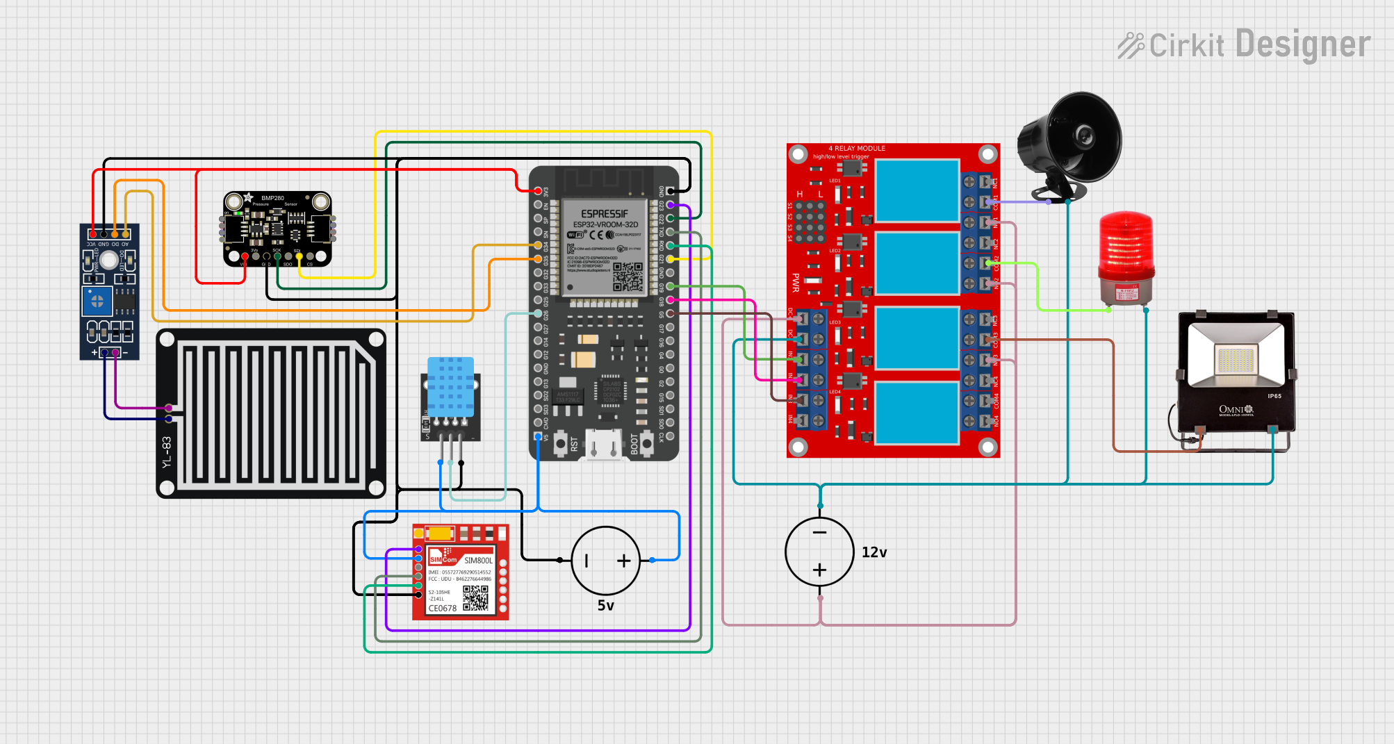
The circuit in question appears to be a sensor and control system, possibly for environmental monitoring and alerting purposes. It includes a variety of sensors (rain sensor, temperature and humidity sensor, barometric pressure sensor), a microcontroller (ESP32), a GSM module (Sim800l), a relay module for controlling external devices, and indicators (red light, siren, flood lights). The circuit is powered by two DC power sources.
Component List
YL-83 Rain Sensor - Detection Board
- A sensor used to detect rainwater.
YL-83 Rain Sensor - Control Board
- The control board for the rain sensor, which provides digital and analog outputs.
ESP32 - 38 pins
- A microcontroller with Wi-Fi and Bluetooth capabilities, used as the central processing unit of the circuit.
Adafruit BMP280
- A sensor for measuring barometric pressure and temperature.
Sim800l
- A GSM module used for cellular communication.
DHT11
- A sensor for measuring temperature and humidity.
DC Power Source
- Provides power to the circuit components.
4 Channel Relay Module
- An interface for controlling up to four high-power devices.
Red Light 220VAC
- An indicator light that operates at 220VAC.
Siren 12V
- An audible alarm device that operates at 12V.
Flood Lights 12V
- High-intensity lights for illumination or signaling, operating at 12V.
Wiring Details
YL-83 Rain Sensor - Detection Board
- POS: Connected to the POS pin of the YL-83 Rain Sensor - Control Board.
- NEG: Connected to the NEG pin of the YL-83 Rain Sensor - Control Board.
YL-83 Rain Sensor - Control Board
- VCC: Connected to the 3V3 pin of the ESP32.
- GND: Common ground with other components.
- DO: Connected to the G35 pin of the ESP32.
- AO: Connected to the G34 pin of the ESP32.
- POS: Connected to the POS pin of the YL-83 Rain Sensor - Detection Board.
- NEG: Connected to the NEG pin of the YL-83 Rain Sensor - Detection Board.
ESP32 - 38 pins
- 3V3: Provides power to the YL-83 Rain Sensor - Control Board and Adafruit BMP280.
- GND: Common ground with other components.
- G34, G35: Connected to the AO and DO pins of the YL-83 Rain Sensor - Control Board, respectively.
- G23: Connected to the NET pin of the Sim800l.
- 5V: Provides power to the DHT11 and Sim800l.
- TXD: Connected to the RXD pin of the Sim800l.
- RXD: Connected to the TXD pin of the Sim800l.
- G26: Connected to the S pin of the DHT11.
- G22: Connected to the SCK/SCL pin of the Adafruit BMP280.
- G21: Connected to the SDI/SDA pin of the Adafruit BMP280.
- G19, G18, G5: Connected to the IN 1, IN 2, and IN 3 pins of the 4 Channel Relay Module, respectively.
Adafruit BMP280
- VCC: Connected to the 3V3 pin of the ESP32.
- GND: Common ground with other components.
- SCK/SCL: Connected to the G22 pin of the ESP32.
- SDI/SDA: Connected to the G21 pin of the ESP32.
Sim800l
- NET: Connected to the G23 pin of the ESP32.
- RST: Not connected.
- VCC: Connected to the 5V pin of the ESP32.
- RXD: Connected to the TXD pin of the ESP32.
- TXD: Connected to the RXD pin of the ESP32.
- GND: Common ground with other components.
DHT11
- 5V: Connected to the 5V pin of the ESP32.
- S: Connected to the G26 pin of the ESP32.
- GND: Common ground with other components.
4 Channel Relay Module
- IN 1, IN 2, IN 3: Connected to the G19, G18, and G5 pins of the ESP32, respectively.
- VCC- (GND): Common ground with other components.
- VCC+: Connected to the Positive pin of the DC Power Source.
- N.O. 1, N.O. 2, N.O. 3: Normally open contacts, connected to the Positive pin of the DC Power Source.
- COM 1, COM 2, COM 3: Connected to the 12V pin of the Siren 12V, the + pin of the Red Light 220VAC, and the 12V pin of the Flood Lights 12V, respectively.
Red Light 220VAC
- -: Connected to the VCC- (GND) pin of the 4 Channel Relay Module.
- +: Connected to the COM 2 pin of the 4 Channel Relay Module.
Siren 12V
- 12V: Connected to the COM 1 pin of the 4 Channel Relay Module.
- GROUND: Connected to the VCC- (GND) pin of the 4 Channel Relay Module.
Flood Lights 12V
- 12V: Connected to the COM 3 pin of the 4 Channel Relay Module.
- GROUND: Connected to the VCC- (GND) pin of the 4 Channel Relay Module.
Documented Code
No code was provided for the microcontroller(s) in the circuit. For a complete documentation, the code should be included to illustrate how the ESP32 interacts with the sensors, GSM module, and relay module, as well as how it processes the sensor data and controls the external devices.