
Arduino-Based 4-Wheel Autonomous and Bluetooth-Controlled Car with GPS and Ultrasonic Sensors
View and Edit Project In Cirkit Designer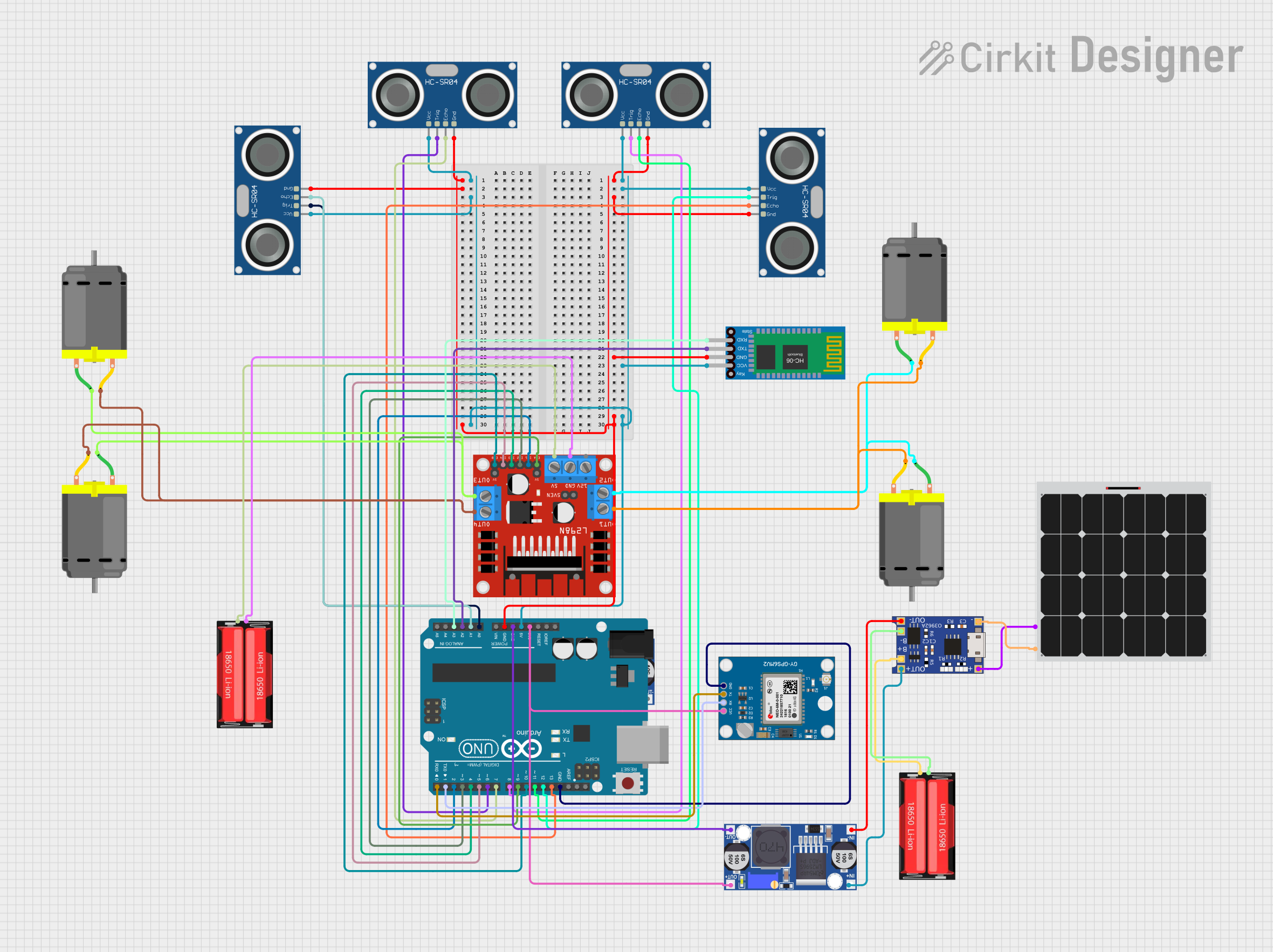
Circuit Documentation
Summary
This document provides a detailed overview of a 4-wheel car circuit controlled via Bluetooth (HC-06) or in autonomous mode. The car uses four ultrasonic sensors for obstacle detection and a NEO-6M GPS module for tracking. The circuit is powered by a 18650 Li-Ion battery and includes a solar panel for charging. The Arduino UNO microcontroller is the brain of the system, interfacing with all sensors, motors, and communication modules.
Component List
L298N DC Motor Driver
- Description: Dual H-Bridge motor driver for controlling DC motors.
- Pins: OUT1, OUT2, 12V, GND, 5V, OUT3, OUT4, 5V-ENA-JMP-I, 5V-ENA-JMP-O, +5V-J1, +5V-J2, ENA, IN1, IN2, IN3, IN4, ENB
HC-SR04 Ultrasonic Sensor
- Description: Ultrasonic distance sensor for obstacle detection.
- Pins: VCC, TRIG, ECHO, GND
Neo 6M GPS Module
- Description: GPS module for tracking.
- Pins: GND, TX, RX, VCC
DC Motor
- Description: Standard DC motor for driving wheels.
- Pins: pin 1, pin 2
18650 Li-Ion Battery
- Description: Rechargeable lithium-ion battery.
- Pins: Positive, Negative
Buck Converter
- Description: Voltage regulator to step down voltage.
- Pins: IN+, IN-, OUT+, OUT-
Bluetooth HC-06
- Description: Bluetooth module for wireless communication.
- Pins: VCC, GND, TXD, RXD
Arduino UNO
- Description: Microcontroller board for controlling the circuit.
- Pins: UNUSED, IOREF, Reset, 3.3V, 5V, GND, Vin, A0, A1, A2, A3, A4, A5, SCL, SDA, AREF, D13, D12, D11, D10, D9, D8, D7, D6, D5, D4, D3, D2, D1, D0
Solar Panel
- Description: Solar panel for charging the battery.
- Pins: +, -
TP4056
- Description: Lithium battery charger module.
- Pins: OUT-, B-, B+, OUT+, IN-, IN+
Wiring Details
L298N DC Motor Driver
- OUT1 to DC Motor pin 2
- OUT2 to DC Motor pin 1
- OUT3 to DC Motor pin 1
- OUT4 to DC Motor pin 2
- GND to 18650 Li-Ion Negative
- 5V to 18650 Li-Ion Positive
- ENB to Arduino UNO D10
- ENA to Arduino UNO D9
- IN4 to Arduino UNO D5
- IN3 to Arduino UNO D4
- IN2 to Arduino UNO D3
- IN1 to Arduino UNO D2
HC-SR04 Ultrasonic Sensor (Front)
- VCC to Arduino UNO 5V
- GND to Arduino UNO GND
- TRIG to Arduino UNO D6
- ECHO to Arduino UNO D7
HC-SR04 Ultrasonic Sensor (Left)
- VCC to Arduino UNO 5V
- GND to Arduino UNO GND
- TRIG to Arduino UNO D8
- ECHO to Arduino UNO D11
HC-SR04 Ultrasonic Sensor (Right)
- VCC to Arduino UNO 5V
- GND to Arduino UNO GND
- TRIG to Arduino UNO A0
- ECHO to Arduino UNO A1
HC-SR04 Ultrasonic Sensor (Back)
- VCC to Arduino UNO 5V
- GND to Arduino UNO GND
- TRIG to Arduino UNO D12
- ECHO to Arduino UNO D13
Neo 6M GPS Module
- VCC to Buck Converter OUT+
- GND to Arduino UNO GND
- TX to Arduino UNO D0
- RX to Arduino UNO D1
DC Motor (Front Left and Front Right)
- pin 1 to L298N DC Motor Driver OUT2
- pin 2 to L298N DC Motor Driver OUT1
DC Motor (Back Left and Back Right)
- pin 1 to L298N DC Motor Driver OUT3
- pin 2 to L298N DC Motor Driver OUT4
18650 Li-Ion Battery
- Positive to L298N DC Motor Driver 5V
- Negative to L298N DC Motor Driver GND
Buck Converter
- IN+ to TP4056 OUT+
- IN- to TP4056 OUT-
- OUT+ to Arduino UNO 3.3V
- OUT- to Arduino UNO GND
Bluetooth HC-06
- VCC to Arduino UNO 5V
- GND to Arduino UNO GND
- TXD to Arduino UNO A2
- RXD to Arduino UNO A3
Solar Panel
- + to TP4056 IN+
- - to TP4056 IN-
TP4056
- OUT+ to Buck Converter IN+
- OUT- to Buck Converter IN-
- B+ to 18650 Li-Ion Positive
- B- to 18650 Li-Ion Negative
Code Documentation
/*
 * Arduino 4-Wheel Car
 * Controlled via Bluetooth (HC-06) or Autonomous Mode
 * Uses 4 Ultrasonic Sensors for Obstacle Detection
 * GPS Tracking via NEO-6M Module
 */

#include <SoftwareSerial.h>

// Pin Definitions
#define TRIG_FRONT 6
#define ECHO_FRONT 7
#define TRIG_LEFT 8
#define ECHO_LEFT 11
#define TRIG_RIGHT A0
#define ECHO_RIGHT A1
#define TRIG_BACK 12
#define ECHO_BACK 13
#define ENA 9
#define ENB 10
#define IN1 2
#define IN2 3
#define IN3 4
#define IN4 5

// Bluetooth and GPS
SoftwareSerial BTSerial(0, 1); // RX, TX
SoftwareSerial GPSSerial(0, 1); // RX, TX

void setup() {
  // Initialize Serial Communication
  Serial.begin(9600);
  BTSerial.begin(9600);
  GPSSerial.begin(9600);

  // Initialize Motor Control Pins
  pinMode(ENA, OUTPUT);
  pinMode(ENB, OUTPUT);
  pinMode(IN1, OUTPUT);
  pinMode(IN2, OUTPUT);
  pinMode(IN3, OUTPUT);
  pinMode(IN4, OUTPUT);

  // Initialize Ultrasonic Sensor Pins
  pinMode(TRIG_FRONT, OUTPUT);
  pinMode(ECHO_FRONT, INPUT);
  pinMode(TRIG_LEFT, OUTPUT);
  pinMode(ECHO_LEFT, INPUT);
  pinMode(TRIG_RIGHT, OUTPUT);
  pinMode(ECHO_RIGHT, INPUT);
  pinMode(TRIG_BACK, OUTPUT);
  pinMode(ECHO_BACK, INPUT);
}

void loop() {
  // Autonomous Mode or Bluetooth Control
  if (BTSerial.available()) {
    char command = BTSerial.read();
    executeCommand(command);
  } else {
    autonomousMode();
  }
}

void executeCommand(char command) {
  switch (command) {
    case 'F': moveForward(); break;
    case 'B': moveBackward(); break;
    case 'L': turnLeft(); break;
    case 'R': turnRight(); break;
    case 'S': stopCar(); break;
  }
}

void autonomousMode() {
  // Implement obstacle detection and avoidance
  if (detectObstacle(TRIG_FRONT, ECHO_FRONT)) {
    stopCar();
    if (detectObstacle(TRIG_LEFT, ECHO_LEFT)) {
      turnRight();
    } else {
      turnLeft();
    }
  } else {
    moveForward();
  }
}

bool detectObstacle(int trigPin, int echoPin) {
  digitalWrite(trigPin, LOW);
  delayMicroseconds(2);
  digitalWrite(trigPin, HIGH);
  delayMicroseconds(10);
  digitalWrite(trigPin, LOW);
  long duration = pulseIn(echoPin, HIGH);
  long distance = duration * 0.034 / 2;
  return distance < 20; // Obstacle within 20 cm