
Circuit Documentation
Summary of the Circuit
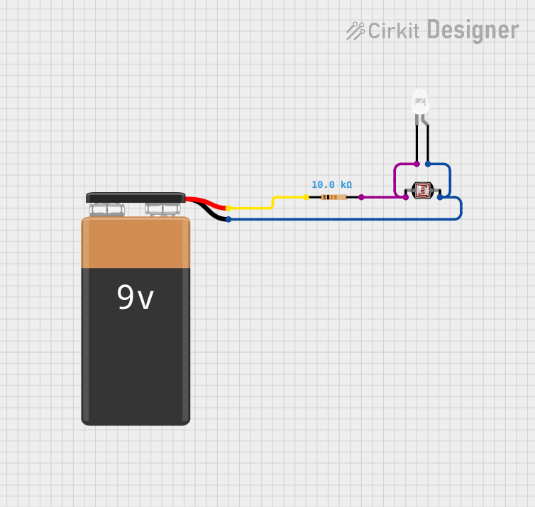
This circuit appears to be a simple light-sensitive LED circuit powered by a 9V battery. The circuit includes a resistor, an LED, a photocell (Light Dependent Resistor, LDR), and a 9V battery. The LED is designed to turn on when the photocell detects a certain level of darkness. The resistor limits the current to the LED to prevent it from burning out. The photocell changes its resistance based on the amount of light it receives, which in turn affects the LED's brightness.
Component List
Resistor
- Description: A passive two-terminal electrical component that implements electrical resistance as a circuit element.
- Purpose: To limit the current flowing through the LED, protecting it from excessive current.
- Properties:
- Resistance: 10,000 Ohms
LED: Two Pin (white)
- Description: A two-pin light-emitting diode that emits white light when powered.
- Purpose: To emit light when the circuit is powered and the photocell detects low light levels.
- Properties: None specified.
Photocell (LDR)
- Description: A light-dependent resistor whose resistance varies with the intensity of light falling upon it.
- Purpose: To vary the current flowing through the circuit based on the ambient light level, controlling the LED brightness.
- Properties: None specified.
9V Battery
- Description: A standard 9-volt battery used as the power source for the circuit.
- Purpose: To provide the necessary voltage and current to power the circuit.
- Properties: None specified.
Wiring Details
Resistor
- Connections:
- One pin is connected to the positive terminal of the 9V battery.
- The other pin is connected to the cathode of the LED and pin 0 of the Photocell (LDR).
LED: Two Pin (white)
- Connections:
- The cathode is connected to pin 2 of the Resistor and pin 0 of the Photocell (LDR).
- The anode is connected to the negative terminal of the 9V battery and pin 1 of the Photocell (LDR).
Photocell (LDR)
- Connections:
- Pin 0 is connected to the cathode of the LED and pin 2 of the Resistor.
- Pin 1 is connected to the anode of the LED and the negative terminal of the 9V battery.
9V Battery
- Connections:
- The positive terminal is connected to pin 1 of the Resistor.
- The negative terminal is connected to the anode of the LED and pin 1 of the Photocell (LDR).
Documented Code
There is no microcontroller or embedded code associated with this circuit as per the provided inputs. Therefore, this section is not applicable to the current documentation.