Cirkit Designer
Your all-in-one circuit design IDE
Home /
Project Documentation
Arduino-Based Load Cell Weight Measurement with HX711 and I2C LCD Display

Circuit Documentation
Summary
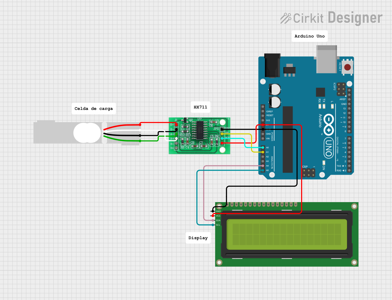
This circuit is designed to interface a load cell with an Arduino UNO microcontroller through an HX711 bridge sensor interface. The load cell's signals are amplified and digitized by the HX711, which then communicates with the Arduino UNO. The Arduino is also connected to a 16x2 I2C LCD display for output. The circuit is powered by the Arduino's 5V supply, which also powers the HX711 and the LCD display. Communication between the Arduino and the LCD is done via the I2C protocol.
Component List
HX711 - Bridge Sensor Interface
- Description: A precision 24-bit analog-to-digital converter (ADC) designed for weigh scales and industrial control applications to interface directly with a bridge sensor.
- Pins: E+, E-, A-, A+, B-, B+, GND, DATA (OUT), SCK (CLOCK IN), 3.3/3.5V Supply
Load Cell - Red/white/black/green
- Description: A transducer that converts force into an electrical signal. This load cell is typically used in weighing systems.
- Pins: E+, A-, E-, A+
16x2 I2C LCD
- Description: A liquid crystal display capable of displaying 16 characters per line across 2 lines. It uses the I2C communication protocol.
- Pins: GND, VCC, SDA, SCL
Arduino UNO
- Description: A microcontroller board based on the ATmega328P. It has 14 digital input/output pins, 6 analog inputs, a 16 MHz quartz crystal, a USB connection, a power jack, an ICSP header, and a reset button.
- Pins: UNUSED, IOREF, Reset, 3.3V, 5V, GND, Vin, A0-A5, SCL, SDA, AREF, D0-D13
Wiring Details
HX711 - Bridge Sensor Interface
- E+ connected to Load Cell E+
- E- connected to Load Cell E-
- A- connected to Load Cell A+
- A+ connected to Load Cell A-
- GND connected to Arduino UNO GND and 16x2 I2C LCD GND
- DATA (OUT) connected to Arduino UNO A1
- SCK (CLOCK IN) connected to Arduino UNO A0
- 3.3/3.5V Supply connected to Arduino UNO 5V and 16x2 I2C LCD VCC
Load Cell - Red/white/black/green
- E+ connected to HX711 E+
- E- connected to HX711 E-
- A+ connected to HX711 A-
- A- connected to HX711 A+
16x2 I2C LCD
- GND connected to Arduino UNO GND and HX711 GND
- VCC connected to Arduino UNO 5V and HX711 3.3/3.5V Supply
- SDA connected to Arduino UNO A4
- SCL connected to Arduino UNO A5
Arduino UNO
- GND connected to HX711 GND and 16x2 I2C LCD GND
- 5V connected to HX711 3.3/3.5V Supply and 16x2 I2C LCD VCC
- A0 connected to HX711 SCK (CLOCK IN)
- A1 connected to HX711 DATA (OUT)
- A4 connected to 16x2 I2C LCD SDA
- A5 connected to 16x2 I2C LCD SCL
Documented Code
Arduino UNO Code (sketch.ino)
void setup() {
  // put your setup code here, to run once:

}

void loop() {
  // put your main code here, to run repeatedly:

}
Note: The provided code is a template and does not include specific functionality. It should be expanded to initialize the HX711 and LCD modules, read data from the HX711, and display the results on the LCD.