
Multi-Sensor Environmental Monitoring System with Wi-Fi Connectivity
View and Edit Project In Cirkit Designer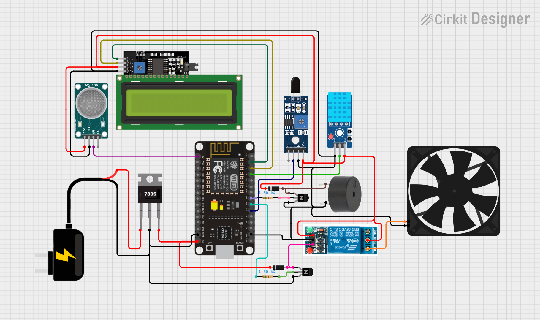
Circuit Documentation
Summary
The circuit in question appears to be a sensor monitoring and display system with an actuation component. It includes various sensors for detecting environmental conditions, a microcontroller for processing sensor data, a display for outputting information, and a relay to control an external device such as a fan. The microcontroller used is an ESP8266 NodeMCU, which is responsible for interfacing with the sensors, driving the display, and controlling the relay based on sensor inputs. The circuit also includes a voltage regulator to provide a stable power supply to the components.
Component List
Sensors
- Sensor SHT113 Flame: A flame detection sensor capable of sensing fire or other sources of heat.
- MQ-136 Sensor Hydrogen Sulfide Gas: A gas sensor designed to detect the presence of hydrogen sulfide in the air.
- DHT11 Sensor V2: A sensor for measuring ambient temperature and humidity.
Display
- LCD Display 16x4 I2C: A 16x4 character LCD display with an I2C interface for showing sensor readings and other information.
Actuators
- Buzzer: An audible alert device that can be triggered by the microcontroller.
- 5v Relay: An electromechanical switch that allows the microcontroller to control higher power devices, such as a fan.
Power Supply and Regulation
- DC Source 9V: A 9V DC power source for the circuit.
- 7805 Voltage Regulator: A voltage regulator that outputs a stable 5V from a higher voltage input.
Output Device
- Fan: An external device that can be turned on or off by the relay.
Additional Components
- NPN Transistor (CBE): A bipolar junction transistor used for switching or amplification.
- Diode: A semiconductor device that allows current to flow in one direction only, used for protection or rectification.
- Resistor: A passive electrical component that provides resistance to the flow of current.
Wiring Details
Sensor SHT113 Flame
- A0: (Not connected in the provided net list)
- D0: Connected to ESP8266 NodeMCU D7
- GND: Connected to the common ground net
- VCC: Connected to the 5V power net
MQ-136 Sensor Hydrogen Sulfide Gas
- VCC: Connected to the 5V power net
- GND: Connected to the common ground net
- A0: Connected to ESP8266 NodeMCU A0
- D0: (Not connected in the provided net list)
DHT11 Sensor V2
- GND: Connected to the common ground net
- DAT: Connected to ESP8266 NodeMCU D3
- VCC: Connected to the 5V power net
LCD Display 16x4 I2C
- SCL: Connected to ESP8266 NodeMCU D1
- SDA: Connected to ESP8266 NodeMCU D2
- VCC: Connected to the 5V power net
- GND: Connected to the common ground net
Buzzer
- PIN: Connected to the anode of a diode, which is connected to the collector of an NPN transistor (CBE)
- GND: Connected to the common ground net
5v Relay
- Normally Open: Connected to the Fan 5V
- Common Terminal: Connected to the DHT11 Sensor V2 VCC
- Normally Closed: (Not connected in the provided net list)
- In: Connected to the anode of a diode, which is connected to the collector of another NPN transistor (CBE)
- GND: Connected to the common ground net
- VCC: Connected to the 5V power net
7805 Voltage Regulator
- Vin: Connected to the DC Source 9V VCC
- Gnd: Connected to the common ground net
- Vout: Connected to the cathode of a diode, which is connected to the ESP8266 NodeMCU VIN
DC Source 9V
- VCC: Connected to the 7805 Voltage Regulator Vin
- GND: Connected to the common ground net
Fan
- GND: Connected to the common ground net
- 5V: Connected to the 5v relay Normally Open
NPN Transistor (CBE)
- Collector: Connected to the anode of a diode and to the relay In or buzzer PIN
- Base: Connected to a resistor, which is connected to ESP8266 NodeMCU D5 or D6
- Emitter: Connected to the common ground net
Diode
- Cathode: Connected to the 7805 Voltage Regulator Vout or to the 5v relay VCC
- Anode: Connected to the NPN Transistor (CBE) collector
Resistor
- Pin1: Connected to ESP8266 NodeMCU D5 or D6
- Pin2: Connected to the NPN Transistor (CBE) base
Documented Code
No code was provided in the input. The code section would typically include the firmware for the ESP8266 NodeMCU, detailing how it reads sensor data, controls the display, and manages the relay and buzzer based on the sensor inputs. It would also include setup and loop functions, along with any necessary function definitions for handling sensor data and actuator control.