STM32F407-Controlled Robotic System with Touch Interface and Motor Actuation
Circuit Documentation
Summary
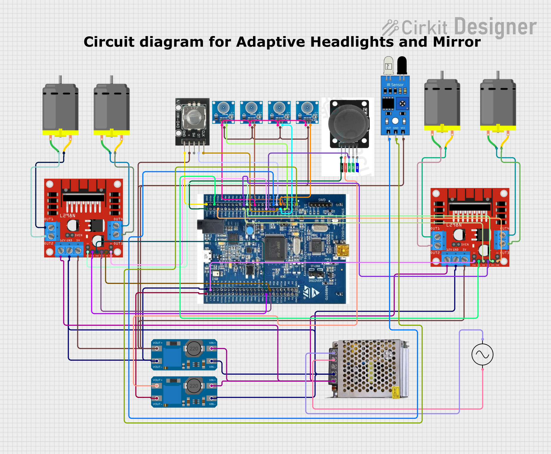
This circuit is designed to control multiple DC motors using L298N motor drivers, with inputs from a rotary encoder, touch sensors, a joystick module, and an IR sensor. The STM32F407 Discovery Kit microcontroller serves as the central processing unit, interfacing with the input devices and controlling the motor drivers. The circuit is powered by a 12V 5A power supply, with voltage regulation provided by MT3608 modules. An AC supply is connected to the power supply to provide the necessary voltage conversion from AC to DC.
Component List
HW-040 Rotary Encoder
- Description: A rotary encoder that provides rotational position feedback.
- Pins: GND, +, SW, DT, CLK
Touch Sensor
- Description: Capacitive touch sensor module.
- Pins: IO, VCC, GND
L298N DC Motor Driver
- Description: A dual H-bridge motor driver capable of driving two DC motors.
- Pins: OUT1, OUT2, 12V, GND, 5V, OUT3, OUT4, 5V-ENA-JMP-I, 5V-ENA-JMP-O, +5V-J1, +5V-J2, ENA, IN1, IN2, IN3, IN4, ENB
POWER SUPPLY 12V 5AMP
- Description: A power supply unit that converts AC to 12V DC output.
- Pins: 220V Positive Pole (AC), 220V Negative Pole (AC), GND, GND (DC), 12V-24V Output (DC)
MT3608
- Description: A DC-DC step-up converter module.
- Pins: VOUT+, VIN+, VOUT-, VIN-
DC Motor
- Description: A standard DC motor for rotational motion.
- Pins: pin 1, pin 2
AC Supply
- Description: An AC power source.
- Pins: +ve, -ve
Joystick Module
- Description: A joystick module that provides two-axis control.
- Pins: SW, VRY, VRX, VCC, GND
IR Sensor
- Description: An infrared sensor for detecting proximity or object presence.
- Pins: out, gnd, vcc
STM32F407 Discovery Kit
- Description: A microcontroller board based on the STM32F407VGT6 microcontroller.
- Pins: GND, PC_0, PC_1, PC_2, PC_3, PA_0, PA_1, PA_2, PA_3, PA_6, PE_9, PE_10, PE_11, PE_12, PE_13, PD_12, PD_13, PE_0, PE_1, PE_2, PE_3, PC_6, 5V, 3V
Wiring Details
HW-040 Rotary Encoder
- GND connected to STM32F407 Discovery Kit GND
- connected to L298N DC motor driver 5V
- SW not connected
- DT connected to STM32F407 Discovery Kit PA_1
- CLK connected to STM32F407 Discovery Kit PA_0
Touch Sensor (Multiple Instances)
- IO connected to STM32F407 Discovery Kit PC_3, PC_0, PC_2, PC_1 respectively
- VCC connected to L298N DC motor driver 5V
- GND connected to STM32F407 Discovery Kit GND
L298N DC Motor Driver (Multiple Instances)
- OUT1, OUT2 connected to DC Motor pin 2, pin 1 respectively
- 12V connected to POWER SUPPLY 12V 5AMP 12V-24V Output (DC)
- GND connected to POWER SUPPLY 12V 5AMP GND (DC)
- 5V connected to various components' VCC (e.g., IR sensor, touch sensors)
- OUT3, OUT4 connected to another DC Motor pin 2, pin 1 respectively
- ENA, IN1, IN2, IN3, IN4, ENB connected to STM32F407 Discovery Kit PE_9, PE_1, PE_0, PE_3, PE_2, PA_6 respectively for the first instance and PC_6, PD_13, PE_12, PE_11, PE_10, PD_12 for the second instance
POWER SUPPLY 12V 5AMP
- 220V Positive Pole (AC) connected to AC Supply +ve
- 220V Negative Pole (AC) connected to AC Supply -ve
- GND (DC) connected to STM32F407 Discovery Kit GND
- 12V-24V Output (DC) connected to L298N DC motor driver 12V
MT3608 (Multiple Instances)
- VOUT+ connected to Joystick module VCC
- VIN+ connected to POWER SUPPLY 12V 5AMP 12V-24V Output (DC)
- VOUT- connected to STM32F407 Discovery Kit GND
- VIN- connected to POWER SUPPLY 12V 5AMP GND (DC)
DC Motor (Multiple Instances)
- pin 1, pin 2 connected to L298N DC motor driver OUT1, OUT2 and OUT3, OUT4 respectively
Joystick Module
- SW not connected
- VRY not connected
- VRX connected to STM32F407 Discovery Kit PA_2
- VCC connected to MT3608 VOUT+
- GND connected to STM32F407 Discovery Kit GND
IR Sensor
- out connected to STM32F407 Discovery Kit PA_3
- gnd connected to STM32F407 Discovery Kit GND
- vcc connected to L298N DC motor driver 5V
Documented Code
Microcontroller Code (STM32F407 Discovery Kit)
#include <107-Arduino-24LCxx.hpp>
#include <107-Arduino-24LCxx.hpp>
#include <107-Arduino-24LCxx.hpp>

void setup() {
  // put your setup code here, to run once:

}

void loop() {
  // put your main code here, to run repeatedly:

}
Filename: sketch.ino
(Note: The code provided is a template and does not contain any functional code specific to the circuit's operation. It includes multiple inclusions of the same library, which is likely an error. The actual implementation code for controlling the motors and reading inputs from the sensors and the rotary encoder should be developed and added to the setup() and loop() functions.)