
ESP32-Based Smart Weather Station with LCD Display and Buzzer Alert
View and Edit Project In Cirkit Designer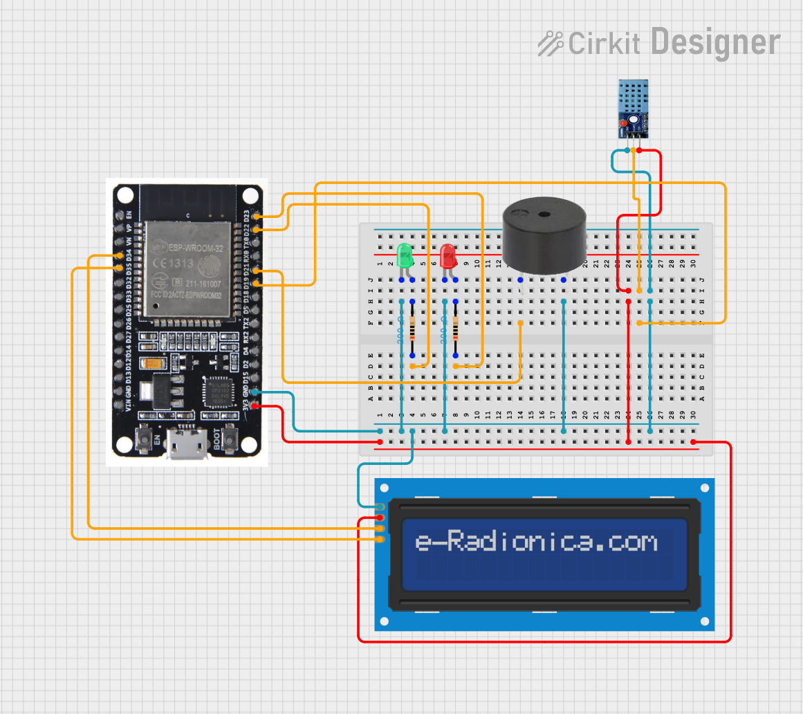
Circuit Documentation
Summary
This circuit involves an ESP32 microcontroller interfacing with various components including a buzzer, two LEDs (red and green), a DHT11 temperature and humidity sensor, and a 16x2 I2C LCD screen. The circuit is designed to read environmental data, display it on the LCD, and provide visual and auditory feedback through the LEDs and buzzer.
Component List
ESP32
- Description: A powerful microcontroller with built-in Wi-Fi and Bluetooth capabilities.
- Pins: EN, VP, VN, D34, D35, D32, D33, D25, D26, D27, D14, D12, D13, GND, VIN, 3V3, D15, D2, D4, RX2, TX2, D5, D18, D19, D21, RX0, TX0, D22, D23, BOOT
Buzzer
- Description: An audio signaling device.
- Pins: PIN, GND
LED: Two Pin (red)
- Description: A red light-emitting diode.
- Pins: cathode, anode
LED: Two Pin (green)
- Description: A green light-emitting diode.
- Pins: cathode, anode
Resistor (200 Ohms)
- Description: A resistor with a resistance of 200 Ohms.
- Pins: pin1, pin2
DHT11
- Description: A temperature and humidity sensor.
- Pins: VCC, GND, DATA
LCD screen 16x2 I2C
- Description: A 16x2 character LCD screen with I2C interface.
- Pins: SCL, SDA, VCC, GND
Wiring Details
ESP32
GND is connected to:
- GND of the green LED
- GND of the red LED
- GND of the buzzer
- GND of the DHT11 sensor
- GND of the LCD screen
D22 is connected to pin1 of a 200 Ohm resistor.
D23 is connected to pin1 of another 200 Ohm resistor.
D21 is connected to the PIN of the buzzer.
3V3 is connected to:
- VCC of the DHT11 sensor
- VCC of the LCD screen
D19 is connected to the DATA pin of the DHT11 sensor.
D34 is connected to the SDA pin of the LCD screen.
D35 is connected to the SCL pin of the LCD screen.
Buzzer
- PIN is connected to D21 of the ESP32.
- GND is connected to GND of the ESP32.
LED: Two Pin (red)
- cathode is connected to GND of the ESP32.
- anode is connected to pin2 of a 200 Ohm resistor.
LED: Two Pin (green)
- cathode is connected to GND of the ESP32.
- anode is connected to pin2 of another 200 Ohm resistor.
Resistor (200 Ohms)
- pin1 of the first resistor is connected to D22 of the ESP32.
- pin2 of the first resistor is connected to the anode of the red LED.
- pin1 of the second resistor is connected to D23 of the ESP32.
- pin2 of the second resistor is connected to the anode of the green LED.
DHT11
- VCC is connected to 3V3 of the ESP32.
- GND is connected to GND of the ESP32.
- DATA is connected to D19 of the ESP32.
LCD screen 16x2 I2C
- SCL is connected to D35 of the ESP32.
- SDA is connected to D34 of the ESP32.
- VCC is connected to 3V3 of the ESP32.
- GND is connected to GND of the ESP32.
Code
No code was provided for this circuit.