
Circuit Documentation
Summary of the Circuit
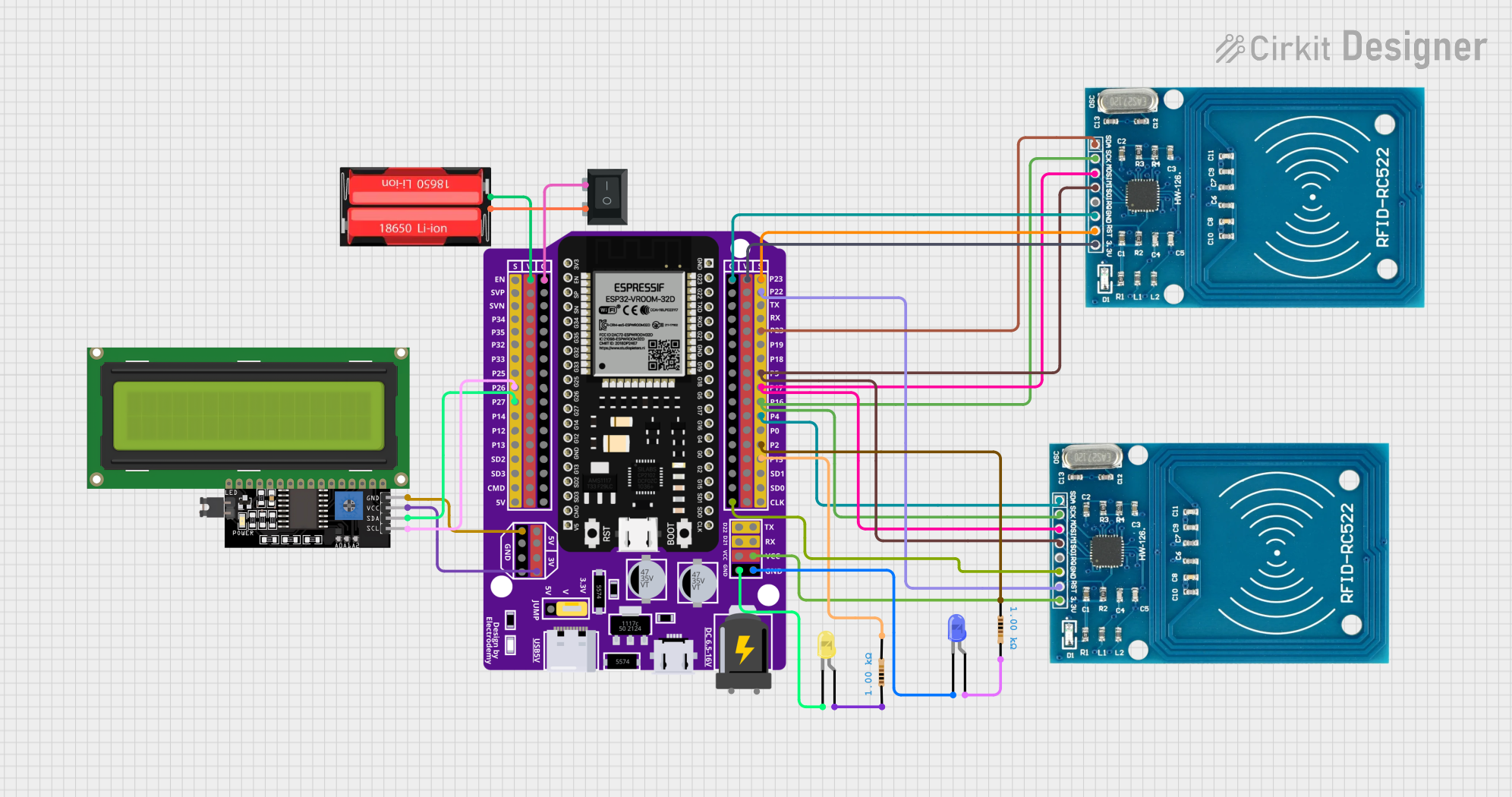
This circuit appears to be designed for an RFID-based system, utilizing an ESP32 microcontroller as the central processing unit. The ESP32 is connected to two RFID-RC522 modules, which are commonly used for RFID tag reading. Additionally, the circuit includes a 16x4 LCD display with an I2C interface for output, two LEDs (blue and yellow) with current-limiting resistors for status indication, a single-cell 18650 Li-Ion battery for power supply, and a rocker switch (SPST) to control the power flow.
Component List
Microcontroller
- ESP32 - 38 pins Expansion Board: A microcontroller with Wi-Fi and Bluetooth capabilities, featuring a wide range of GPIO pins for interfacing with various peripherals.
RFID Modules
- RFID-RC522: Two instances of an RFID reader module capable of reading MIFARE tags and cards, operating at 13.56 MHz.
Display
- LCD Display 16x4 I2C: A 16x4 character LCD display with an I2C interface for displaying information.
LEDs
- LED: Two Pin (blue): A blue LED for status indication.
- LED: Two Pin (yellow): A yellow LED for status indication.
Resistors
- Resistor: Two 1000 Ohm resistors used to limit current through the LEDs.
Power Supply
- 18650 Li-Ion: A rechargeable lithium-ion battery cell providing power to the circuit.
Switch
- Rocker Switch (SPST): A single-pole single-throw rocker switch used to control the power supply to the circuit.
Wiring Details
ESP32 - 38 pins Expansion Board
- VCC connected to RFID-RC522 VCC (3.3V) and 18650 Li-Ion Positive.
- GND connected to RFID-RC522 GND, LCD Display GND, LEDs cathode through resistors, and Rocker Switch pin 2.
- P22 connected to RFID-RC522 RST.
- P5 connected to RFID-RC522 MISO.
- P17 connected to RFID-RC522 MOSI.
- P16 connected to RFID-RC522 SCK.
- P4 and P23 connected to RFID-RC522 SDA.
- P26 connected to LCD Display SCL.
- P27 connected to LCD Display SDA.
- 3V connected to LCD Display VCC.
- P15 and P2 connected to resistors pin 2 and pin 1 respectively, for current limiting to LEDs.
RFID-RC522
- Two instances with connections to ESP32 as detailed above.
LCD Display 16x4 I2C
- SCL connected to ESP32 P26.
- SDA connected to ESP32 P27.
- VCC connected to ESP32 3V.
- GND connected to ESP32 GND.
LEDs
- Blue LED anode connected to resistor pin 2, cathode connected to ESP32 GND.
- Yellow LED anode connected to resistor pin 1, cathode connected to ESP32 GND.
Resistors
- Two 1000 Ohm resistors, each connected between an LED anode and ESP32 GPIO (P15 for yellow LED, P2 for blue LED).
18650 Li-Ion
- Positive connected to ESP32 VCC.
- Negative connected to Rocker Switch pin 1.
Rocker Switch (SPST)
- Pin 1 connected to 18650 Li-Ion Negative.
- Pin 2 connected to ESP32 GND.
Documented Code
No code has been provided for the microcontroller. The documentation of the code would typically include a description of the functionality, setup, and main loop, along with any functions or libraries used. Since no code is available, this section remains empty.