
Arduino UNO-Based Smart Soil Moisture Monitoring System with LCD Display and Automatic Water Pump Control
View and Edit Project In Cirkit Designer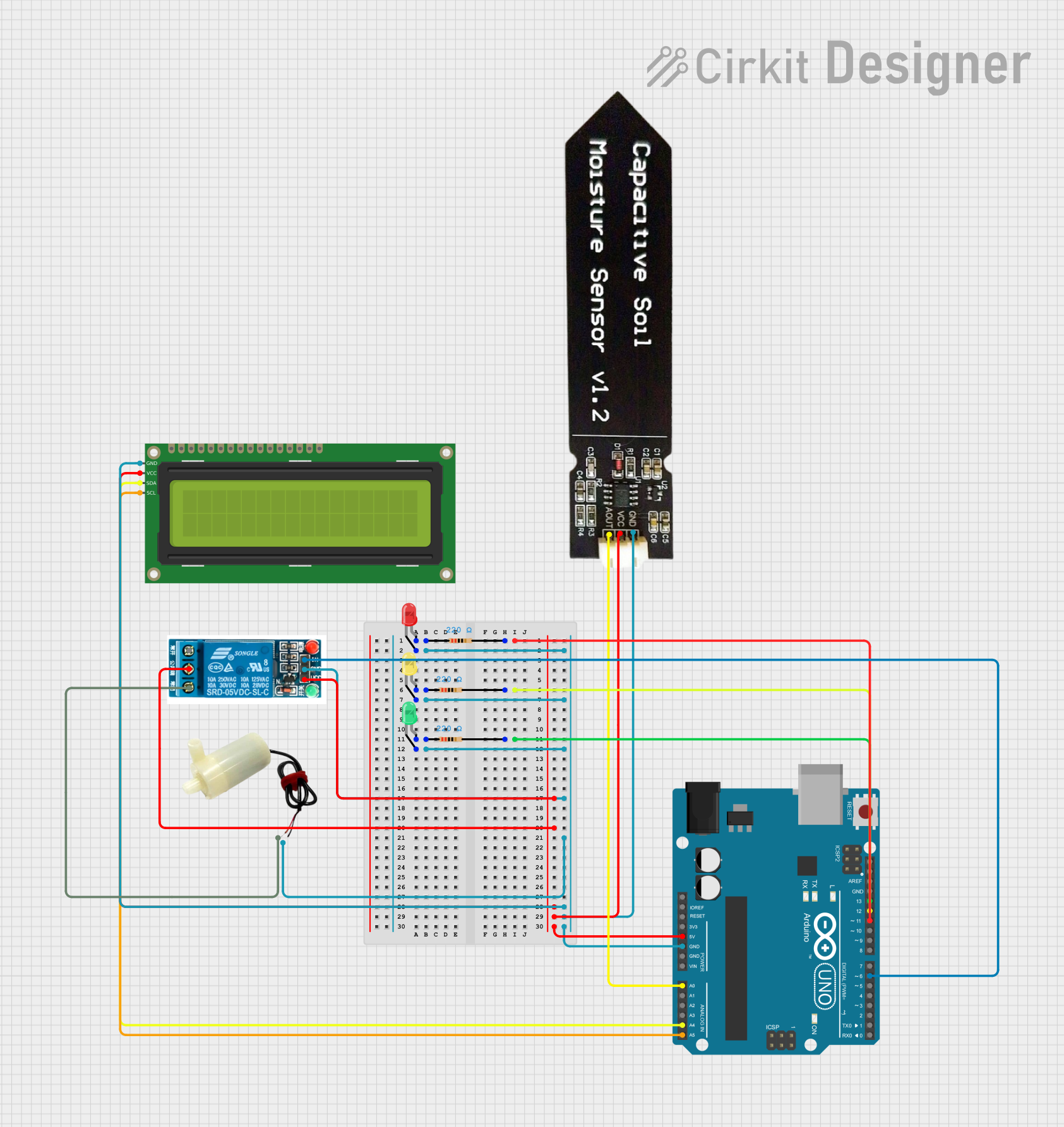
Circuit Documentation
Summary
This circuit is designed to monitor soil moisture levels using a capacitive soil moisture sensor and display the status on a 16x2 I2C LCD. Depending on the moisture level, it controls a water pump via a 5V relay and indicates the status using three LEDs (green, yellow, and red). The entire system is controlled by an Arduino UNO.
Component List
Capacitive Soil Moisture Sensor V1.2
- Pins: GND, VCC, AOUT
- Description: Measures the moisture level in the soil.
- Purpose: Provides analog output corresponding to soil moisture level.
Arduino UNO
- Pins: UNUSED, IOREF, Reset, 3.3V, 5V, GND, Vin, A0, A1, A2, A3, A4, A5, SCL, SDA, AREF, D13, D12, D11, D10, D9, D8, D7, D6, D5, D4, D3, D2, D1, D0
- Description: Microcontroller board based on the ATmega328P.
- Purpose: Central control unit for the circuit.
16x2 I2C LCD
- Pins: GND, VCC, SDA, SCL
- Description: 16x2 character LCD with I2C interface.
- Purpose: Displays the soil moisture status and sensor readings.
LED: Two Pin (green)
- Pins: cathode, anode
- Description: Green LED.
- Purpose: Indicates that the soil is wet.
LED: Two Pin (red)
- Pins: cathode, anode
- Description: Red LED.
- Purpose: Indicates that the soil is dry and needs water.
LED: Two Pin (yellow)
- Pins: cathode, anode
- Description: Yellow LED.
- Purpose: Indicates that the soil moisture is sufficient.
Resistor (220 Ohms)
- Pins: pin1, pin2
- Description: 220 Ohm resistor.
- Purpose: Current limiting resistor for LEDs.
5V Relay
- Pins: Normally Open, Common terminal, Normally Closed, In, GND, VCC
- Description: 5V relay module.
- Purpose: Controls the water pump based on soil moisture level.
5V Mini Water Pump
- Pins: positive pin, negative pin
- Description: Small water pump.
- Purpose: Waters the soil when moisture level is low.
Wiring Details
Capacitive Soil Moisture Sensor V1.2
- GND connected to Arduino UNO GND
- VCC connected to Arduino UNO 5V
- AOUT connected to Arduino UNO A0
Arduino UNO
- GND connected to:
- Capacitive Soil Moisture Sensor V1.2 GND
- 16x2 I2C LCD GND
- 5V Relay GND
- 5V Mini Water Pump negative pin
- LED (green) cathode
- LED (red) cathode
- LED (yellow) cathode
- 5V connected to:
- Capacitive Soil Moisture Sensor V1.2 VCC
- 16x2 I2C LCD VCC
- 5V Relay VCC
- A0 connected to Capacitive Soil Moisture Sensor V1.2 AOUT
- A4 connected to 16x2 I2C LCD SDA
- A5 connected to 16x2 I2C LCD SCL
- D6 connected to 5V Relay In
- D11 connected to Resistor pin2 (for green LED)
- D12 connected to Resistor pin2 (for yellow LED)
- D13 connected to Resistor pin2 (for red LED)
16x2 I2C LCD
- GND connected to Arduino UNO GND
- VCC connected to Arduino UNO 5V
- SDA connected to Arduino UNO A4
- SCL connected to Arduino UNO A5
LED: Two Pin (green)
- cathode connected to Arduino UNO GND
- anode connected to Resistor pin1
LED: Two Pin (red)
- cathode connected to Arduino UNO GND
- anode connected to Resistor pin1
LED: Two Pin (yellow)
- cathode connected to Arduino UNO GND
- anode connected to Resistor pin1
Resistor (220 Ohms)
- pin1 connected to:
- LED (green) anode
- LED (red) anode
- LED (yellow) anode
- pin2 connected to:
- Arduino UNO D11 (for green LED)
- Arduino UNO D12 (for yellow LED)
- Arduino UNO D13 (for red LED)
5V Relay
- GND connected to Arduino UNO GND
- VCC connected to Arduino UNO 5V
- In connected to Arduino UNO D6
- Common terminal connected to 5V Relay VCC
- Normally Closed connected to 5V Mini Water Pump positive pin
5V Mini Water Pump
- positive pin connected to 5V Relay Normally Closed
- negative pin connected to Arduino UNO GND
Code Documentation
#include <Wire.h>
#include <LiquidCrystal_I2C.h>

const int pinDigital = A0;  // Initialize sensor pin
const int relay = 6;        // Initialize relay pin
const int ledGreen = 11;    // Initialize green LED pin
const int ledYellow = 12;   // Initialize yellow LED pin
const int ledRed = 13;      // Initialize red LED pin

// Initialize LCD with I2C address 0x27 and size 16x2
LiquidCrystal_I2C lcd(0x27, 16, 2);

void setup() {
  Serial.begin(9600);          // Start serial monitor

  // Initialize LCD
  lcd.init();
  lcd.backlight();

  pinMode(pinDigital, INPUT);   // Set A0 as input
  pinMode(relay, OUTPUT);       // Set pin 6 as output
  pinMode(ledGreen, OUTPUT);    // Set pin 11 as output
  pinMode(ledYellow, OUTPUT);   // Set pin 12 as output
  pinMode(ledRed, OUTPUT);      // Set pin 13 as output
}

void loop() {
  int dataAnalog = analogRead(pinDigital);  // Read value from sensor pin

  // Print result to serial monitor
  Serial.print("A0 : ");
  Serial.print(dataAnalog);

  // Clear LCD before writing
  lcd.clear();

  // If A0 value is less than 250, print message and turn on green LED, turn off yellow, red LEDs and relay
  if (dataAnalog < 250) {
    Serial.println(". Media Masih Basah");
    digitalWrite(ledGreen, HIGH);
    digitalWrite(ledYellow, LOW);
    digitalWrite(ledRed, LOW);
    digitalWrite(relay, LOW);

    // Display status on LCD
    lcd.setCursor(0, 0);
    lcd.print("Status: Basah");
    lcd.setCursor(0, 1);
    lcd.print("Nilai: ");
    lcd.print(dataAnalog);
  }

  // If A0 value is less than or equal to 400, print message and turn on yellow LED and relay, turn off green and red LEDs
  else if (dataAnalog <= 400) {
    Serial.println(". Kelembaban Tanah Masih Cukup");
    digitalWrite(ledGreen, LOW);
    digitalWrite(ledYellow, HIGH);
    digitalWrite(ledRed, LOW);

    // Display status on LCD
    lcd.setCursor(0, 0);
    lcd.print("Status: Cukup");
    lcd.setCursor(0, 1);
    lcd.print("Nilai: ");
    lcd.print(dataAnalog);
  }

  // If A0 value is greater than 400, print message and turn on red LED and relay
  else if(dataAnalog > 400){
    Serial.println(". Perlu Tambahan Air");
    digitalWrite(ledGreen, LOW);
    digitalWrite(ledYellow, LOW);
    digitalWrite(ledRed, HIGH);
    digitalWrite(relay, HIGH);

    // Display status on LCD
    lcd.setCursor(0, 0);
    lcd.print("Status: Kering");
    lcd.setCursor(0, 1);
    lcd.print("Nilai: ");
    lcd.print