Cirkit Designer
Your all-in-one circuit design IDE
Home /
Project Documentation
ESP8266 WiFi Module and Flipper Zero GPIO Interaction Project
Circuit Documentation
Summary
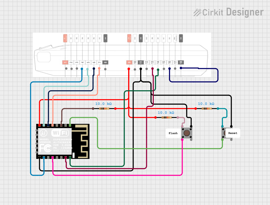
The circuit in question appears to be designed for interfacing an ESP8266 ESP-12F WiFi module with a Flipper Zero GPIO for various control and communication purposes. The circuit includes pushbuttons and resistors, likely for input control and pull-up/pull-down configurations. The ESP8266 module is a popular WiFi module used for IoT applications, and the Flipper Zero is a multi-tool device for hardware hacking. The circuit likely serves as a prototype for wireless control or data exchange.
Component List
ESP8266 ESP-12F WiFi Module
- Description: A WiFi module that provides internet connectivity to microcontroller-based projects.
- Pins: GND, GPIO15, GPIO2, GPIO0, GPIO4, GPIO5, RXD0, TXD0, RST, ADC0, EN, GPIO16, GPIO14, GPIO12, GPIO13, VCC, SCLK, MOSI, GPIO10, GPIO9, MISO, CS0
Resistor (10k Ohms)
- Description: A passive two-terminal electrical component that implements electrical resistance as a circuit element.
- Value: 10,000 Ohms
Flipper Zero GPIO
- Description: General Purpose Input/Output interface for the Flipper Zero device.
- Pins: 5, PA7, PA6, PA4, PB3, PB2, PC3, GBD, 3.3V, PA14, GND, PA13, PB6, PB7, PC1, PC0, PB14
Pushbutton
- Description: A simple switch mechanism for controlling some aspect of a machine or a process.
- Pins: Pin 3 (out), Pin 4 (out), Pin 1 (in), Pin 2 (in)
Wiring Details
ESP8266 ESP-12F WiFi Module
- GND connected to Flipper Zero GPIO GND and Pushbutton Pin 3 (out)
- GPIO15 connected to Flipper Zero GPIO PA4
- GPIO0 connected to Pushbutton Pin 2 (in)
- RXD0 connected to Flipper Zero GPIO PB6
- TXD0 connected to Flipper Zero GPIO PB7
- RST connected to Pushbutton Pin 2 (in)
- EN connected to one end of a 10k Ohm Resistor
- GPIO14 connected to Flipper Zero GPIO PC3
- GPIO12 connected to Flipper Zero GPIO PB2
- GPIO13 connected to Flipper Zero GPIO PB3
- VCC connected to Flipper Zero GPIO 3.3V, and the other ends of three 10k Ohm Resistors
Resistor (10k Ohms)
- One resistor connected between Flipper Zero GPIO 3.3V and ESP8266 ESP-12F WiFi Module VCC
- One resistor connected between Flipper Zero GPIO 3.3V and Pushbutton Pin 1 (in)
- One resistor connected between ESP8266 ESP-12F WiFi Module EN and an unspecified net (possibly for pull-up configuration)
Flipper Zero GPIO
- GND connected to ESP8266 ESP-12F WiFi Module GND and Pushbutton Pin 3 (out)
- PA4 connected to ESP8266 ESP-12F WiFi Module GPIO15
- PB6 connected to ESP8266 ESP-12F WiFi Module RXD0
- PB7 connected to ESP8266 ESP-12F WiFi Module TXD0
- PC3 connected to ESP8266 ESP-12F WiFi Module GPIO14
- PB2 connected to ESP8266 ESP-12F WiFi Module GPIO12
- PB3 connected to ESP8266 ESP-12F WiFi Module GPIO13
- 3.3V connected to ESP8266 ESP-12F WiFi Module VCC and two ends of 10k Ohm Resistors
- PC0 connected to Flipper Zero GPIO GND
Pushbutton
- Pin 3 (out) connected to ESP8266 ESP-12F WiFi Module GND and Flipper Zero GPIO GND
- Pin 2 (in) connected to ESP8266 ESP-12F WiFi Module GPIO0 and RST
- Pin 1 (in) connected to one end of a 10k Ohm Resistor
Documented Code
There is no code provided for the microcontrollers in the circuit. If code is later provided, it should be documented here with explanations of its functionality and how it interacts with the hardware components listed above.