ESP32-Based Multi-Sensor Interface with GSM and Display
Circuit Documentation
Summary
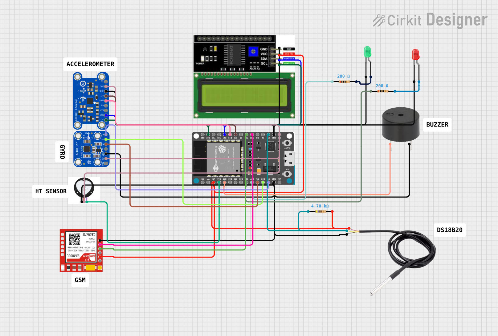
The circuit in question appears to be a multifunctional device incorporating various sensors and output devices, controlled by an ESP32 Devkit V1 microcontroller. The circuit includes an LCD I2C display for user interface, a PULSE SENSOR and a DS18B20 temperature sensor for data acquisition, an Adafruit L3GD20H Triple-Axis Gyro and an Adafruit ADXL377 accelerometer for motion sensing, a SIM800L module for cellular communication, and LEDs and a buzzer for notifications or status indications. The circuit is powered by a 3.3V supply from the ESP32, which is common for many of the components, and includes resistors for current limiting and signal conditioning.
Component List
LCD I2C Display
- Description: A display module for user interface, communicates via I2C.
- Pins: GND, VCC, SDA, SCL
LED: Two Pin (red)
- Description: A red LED for indication purposes.
- Pins: cathode, anode
LED: Two Pin (green)
- Description: A green LED for indication purposes.
- Pins: cathode, anode
Resistor (200 Ohms)
- Description: A resistor for current limiting or voltage division.
- Value: 200 Ohms
Adafruit L3GD20H Triple-Axis Gyro Breakout Board
- Description: A sensor for measuring angular rates.
- Pins: SCL/SPC, SDA/SDI/SDO, SDO/SAO, CS, DRDY/INT2, INT1, GND, +3V3, VIN
Sim800l
- Description: A cellular communication module.
- Pins: NET, RST, VCC, RXD, TXD, GND
ESP32 Devkit V1
- Description: A microcontroller development board based on the ESP32.
- Pins: 3V3, GND, D15, D2, D4, RX2, TX2, D5, D18, D19, D21, RX0, TX0, D22, D23, EN, VP, VN, D34, D35, D32, D33, D25, D26, D27, D14, D12, D13, VIN
Buzzer
- Description: An audio signaling device.
- Pins: PIN, GND
PULSE SENSOR
- Description: A sensor for detecting heart rate.
- Pins: (Not specified)
DS18B20
- Description: A temperature sensor.
- Pins: signal, GND, vcc
Adafruit ADXL377
- Description: A high-G accelerometer.
- Pins: VIN, 3.3V, GND, SELFTEST, ZOUT, YOUT, XOUT
Resistor (4700 Ohms)
- Description: A resistor for current limiting or voltage division.
- Value: 4700 Ohms
Comments
- Description: Comments are placeholders for additional information or notes.
Wiring Details
LCD I2C Display
- GND connected to ESP32 GND
- VCC connected to ESP32 VN through a 4700 Ohm resistor
- SDA connected to ESP32 D21
- SCL connected to ESP32 D22
LED: Two Pin (red)
- Cathode connected to ESP32 GND
- Anode connected to ESP32 D26 through a 200 Ohm resistor
LED: Two Pin (green)
- Cathode connected to ESP32 GND
- Anode connected to ESP32 D27 through a 200 Ohm resistor
Adafruit L3GD20H Triple-Axis Gyro Breakout Board
- SCL/SPC connected to ESP32 D22
- SDA/SDI/SDO connected to ESP32 D21
- GND connected to ESP32 GND
- +3V3 connected to ESP32 3V3
- INT1 connected to ESP32 D18
- DRDY/INT2 connected to ESP32 D19
Sim800l
- GND connected to ESP32 GND
- VCC connected to ESP32 VN through a 4700 Ohm resistor
- RXD connected to ESP32 TX2
- TXD connected to ESP32 RX2
ESP32 Devkit V1
- 3V3 supplies power to PULSE SENSOR, Adafruit L3GD20H, and Adafruit ADXL377
- GND is common for all components requiring a ground connection
- Digital and communication pins are connected as specified in individual component sections
Buzzer
- PIN connected to ESP32 D35
- GND connected to ESP32 GND
PULSE SENSOR
- Connected to ESP32 3V3 and GND
- Data connection to ESP32 D34 (assumed based on typical usage)
DS18B20
- Signal connected to ESP32 D15 through a 4700 Ohm resistor
- GND connected to ESP32 GND
- VCC connected to ESP32 VN through a 4700 Ohm resistor
Adafruit ADXL377
- VIN connected to ESP32 3V3
- GND connected to ESP32 GND
- ZOUT connected to ESP32 D14
- YOUT connected to ESP32 D12
- XOUT connected to ESP32 D13
Documented Code
No code was provided for the microcontroller. Typically, the code would initialize the peripherals, configure the I/O pins, set up communication protocols (e.g., I2C, UART), and implement the logic for sensor data acquisition, processing, and output control (e.g., display, LEDs, buzzer). Without the code, we cannot document the software part of the circuit.